
Monostable to bistable relay with momentary switch

The described circuit is a monostable relay driver that utilizes a momentary switch to control a relay operation. The circuit is powered by a 24V source and is designed to operate a 12V relay. The main components include two transistors (Q1 and Q2), a capacitor, and the relay itself.
Upon pressing the momentary switch, transistor Q1 is activated, allowing current to flow through it. This action causes the capacitor to charge while simultaneously shorting the relay coil, preventing it from energizing during this initial phase. Once the switch is released, the capacitor continues to supply power to Q1 until the relay switch (designated as 10-6) closes. This transition allows the relay to turn on, providing the desired output.
The circuit incorporates an additional feature through the use of transistor Q2. When the switch is pressed a second time, Q2 is activated, which causes Q1 to turn off due to the current flowing through the collector of Q2. However, the relay coil remains energized by Q2, maintaining the relay's active state. Upon releasing the switch, Q2 will deactivate, but Q1 will reactivate approximately 10 milliseconds later. The rapid response of the relay coil allows the circuit to revert to its initial state before Q1 can fully turn on, effectively creating a bistable relay behavior.
This design is particularly advantageous in applications such as automotive systems where a relay needs to maintain its state until power is interrupted. The ability of the relay to return to an off state upon power loss adds a layer of safety and reliability to the circuit, making it suitable for various automotive and industrial applications where momentary control is required. The use of transistors for switching also allows for low-power control signals to manage higher voltage relay operations efficiently.This circuit could be used to drive a monostable relay by a singol momentary switch. Powered by 24 Volts it works for a 12 Volts relay. When the button is pressed Q1 is energized and the capacitor charges, while the relay coil is shorted. Once the button is released the relay turns on. Note that Q1 is powered by the capacitor until the relay switch (10-6) closes.
Since the exchange switch is now closed between 9 and 5, when the button is pressed again Q2 is energized. Q1 switches off due to the current which flows through Q2 collector, but the relay coil is still energized by Q2.
When the button is released Q2 switches off, while Q1 would back on 10 milliseconds later. But the relay coil is faster, so the circuit backs to the start condition. Therefore the circuit works as a mechanical bistable relay, but the relay backs off if you cut the power supply. That may be an useful feature, for example in the automotive field.
Related Circuits
This is a single channel (on / off) universal switch that may be used with any Infra Red remote control using 36-38kHz. (This is a very common remote handset frequency). Any "button" of any remote control may be used...

Automatic Headlight Brightness Switch Circuit. Driving on the highway with high-beam headlights can significantly enhance visibility; however, it can also pose a blinding hazard for other drivers. This straightforward circuit can be integrated into your headlight system. This automatic headlight...
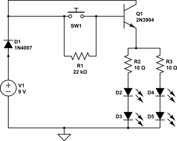
A circuit has been constructed that functions unexpectedly. The circuit utilizes red 5mm LEDs as diodes, a 3904 NPN transistor, and resistors as indicated in the schematic. Logically, pressing the push button normally open (PBNO) should result in the...
The value may vary based on the switching frequency, environmental conditions, and required reliability level; therefore, it is advisable to verify this with the actual load. The maximum ambient temperature represents the highest temperature that can meet the coil...
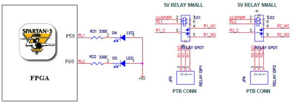
The Spartan-3 board features external 5V relay interfacing, as depicted in the accompanying figure. The ULN2803 is utilized as a driver for the FPGA I/O lines, with the driver outputs connected to the relay modules. A PTB connector is...
The circuit detects the mains current supplied to a master device and controls the on/off state of slave equipment. This functionality is particularly beneficial in environments such as hi-fi systems or home computers, where multiple peripheral devices can be...