
Automatic Headlight Brightness Switch

This automatic headlight brightness switch circuit is designed to enhance driving safety by automatically adjusting the headlight intensity based on ambient light conditions. The circuit typically consists of a light-dependent resistor (LDR), a comparator, and a relay or transistor switch.
When the vehicle is in low light conditions, such as during nighttime or in tunnels, the LDR detects the reduced light levels and sends a signal to the comparator. The comparator then evaluates the input from the LDR against a predefined threshold. If the light level falls below this threshold, the comparator activates the relay or transistor, switching the headlights to high beam.
Conversely, when the vehicle enters a well-lit area, such as urban environments or when approaching other vehicles, the LDR senses the increase in ambient light. The comparator then deactivates the relay or transistor, switching the headlights back to low beam to prevent glare for oncoming drivers.
Additional components may include resistors and capacitors to stabilize the circuit and ensure smooth operation. A diode can also be included to prevent back EMF when the relay is switched off, protecting the circuit from potential damage.
This circuit not only improves driving comfort and safety but also enhances compliance with traffic regulations regarding headlight usage. Proper installation and calibration of the LDR and comparator are crucial for optimal performance, ensuring that the transition between high and low beams occurs seamlessly and effectively.Automatic Headlight Brightness Switch Circuit Driving the highway with your high-beam headlights can really increase your visibility, but can he a blinding hazard for other drivers. This simple circuit can be wired into your hea.. 🔗 External reference
Related Circuits
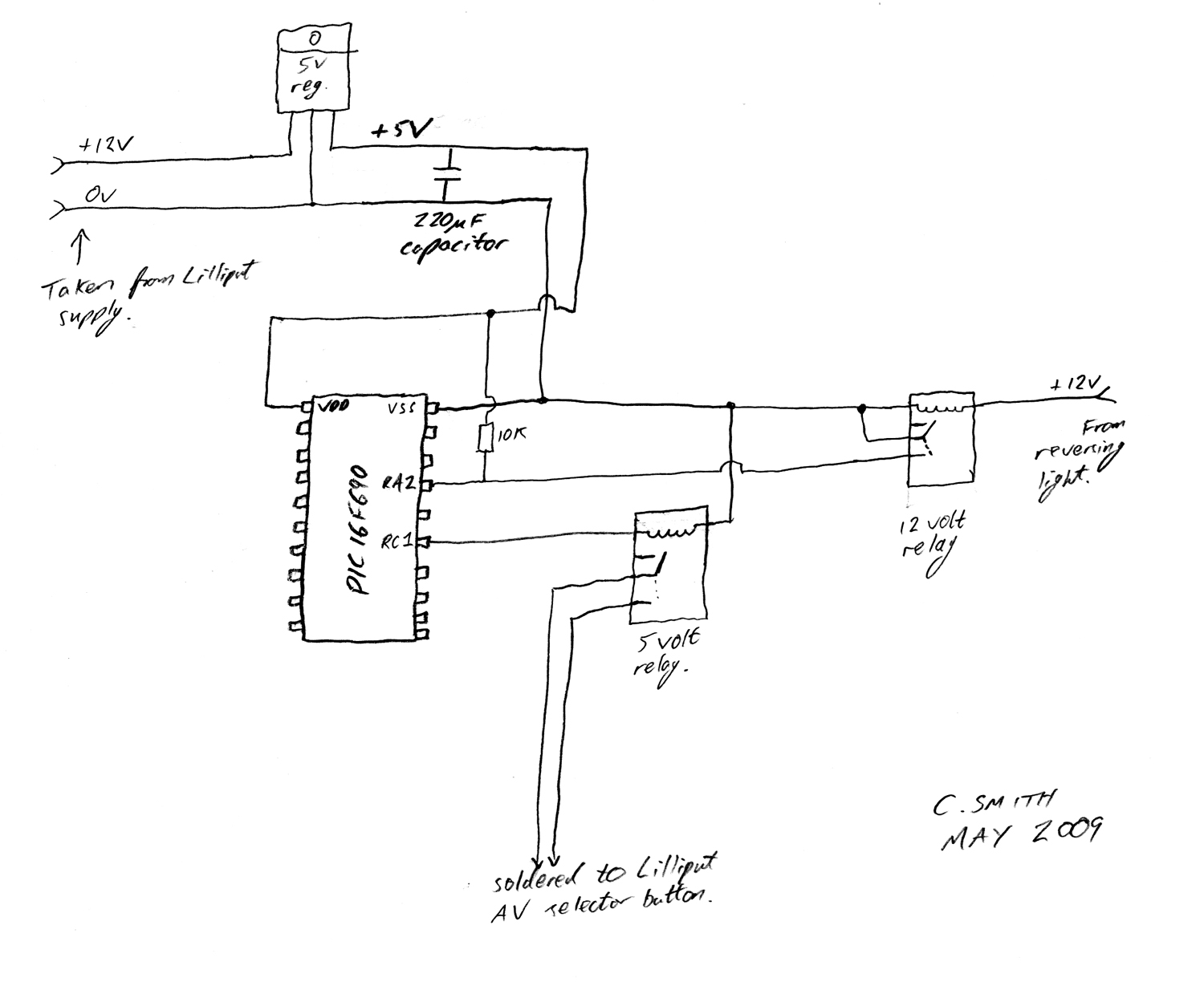
There have been numerous discussions regarding the Lilliput's inability to automatically switch, despite the presence of this feature in the secret menu. The Lilliput display is a versatile device often used in various applications, including professional video production and...
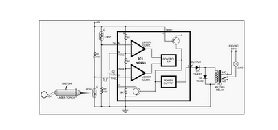
This circuit is designed around a 555 timer and utilizes a minimal number of components. Due to its simplicity, it can be easily constructed and operated by beginners. The circuit leverages the 555 timer IC, which is a versatile and...
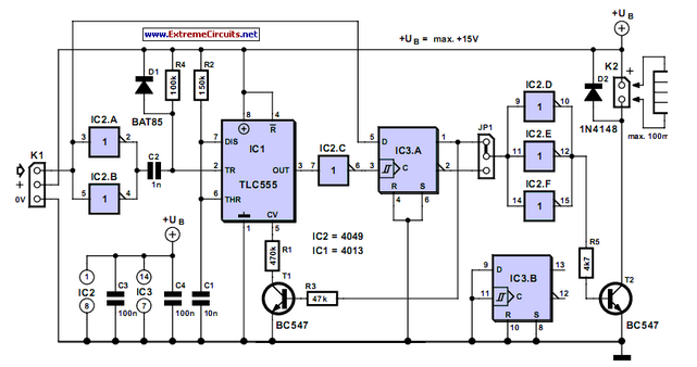
It is sometimes necessary for a remote control (RC) model to incorporate a switching functionality. This can include features such as lights on a model. In the context of remote control models, incorporating switching functionality can significantly enhance user experience...
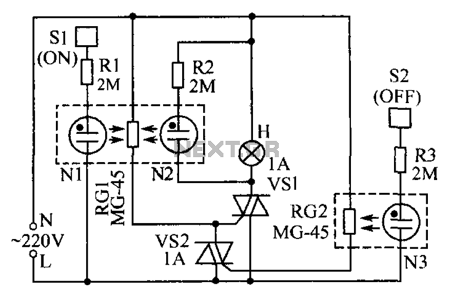
The circuit operates based on the principle that neon tubes N1, N2, and the photosensitive resistor RG1 form an optocoupler. When a finger touches the metal sheet S1, N1 lights up, causing RG1's resistance to decrease. This reduction allows...
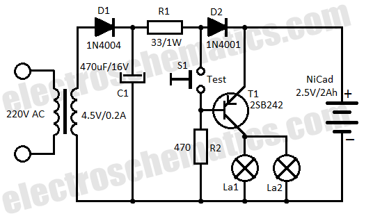
This low-cost automatic emergency lighting circuit activates a lamp during power failures. It is powered by a NiCad battery that is charged by the mains. The automatic emergency lighting circuit is designed to provide illumination during unexpected power outages. The...
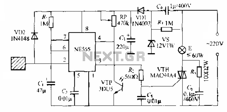
The circuit utilizes a NE553 automatic light sensor composed of 55 groups, allowing lights to turn on when individuals are present and turn off when they leave. The power supply includes VD1, vS, and C, with a 12V DC...
Warning: include(partials/cookie-banner.php): Failed to open stream: Permission denied in /var/www/html/nextgr/view-circuit.php on line 713
Warning: include(): Failed opening 'partials/cookie-banner.php' for inclusion (include_path='.:/usr/share/php') in /var/www/html/nextgr/view-circuit.php on line 713