
More op-amp circuits
For Vin > 0, the equivalent circuit depicted shows that diode D1 is reverse-biased and acts as an open circuit, while D2 is conducting. The feedback loop effectively consists of a single resistor connecting the output of op-amp OA2 to the negative input of op-amp OA1. OA1 and OA2 function together as a single op-amp, making the complete circuit behave like a simple voltage follower, where Vout = Vin. A complication arises in this circuit: at sufficiently high frequencies, both OA1 and OA2 introduce a 90-degree phase shift, which, combined with the 180-degree shift from feeding the signal back to the input of OA1, can lead to instability. A small capacitor, C, is employed to mitigate this issue. The circuit should be assembled with C set to 100 pF initially, and its operation should be verified with various waveforms at a frequency of 1 kHz. The frequency should be increased until the issues that occur when switching from Vin < 0 to Vin > 0 become apparent. The typical switching time should be observed, and modifications to C should be made to improve performance. It should be noted that without C, the circuit becomes unstable when Vin > 0.
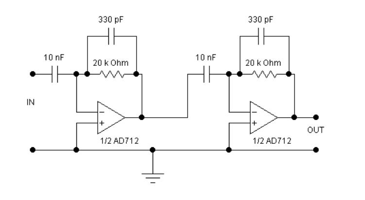
The circuit requires two op-amps, which can be sourced from a single package to conserve power supply connections and facilitate a compact design. The dual op-amp AD712 is recommended for this circuit. The Wien bridge oscillator can be understood by first analyzing the transfer function of the RC network that constitutes the feedback loop. By calculating V2/V1, it is determined that for wRC = 1, the signal at the amplifier's input is precisely in phase with that at the output. If the amplifier’s gain is at least 3 (to compensate for the factor of 1/3 in V2/V1), the circuit will oscillate at a frequency of f = 1/2πRC. When the amplifier's gain exceeds 3, the output amplitude increases until it saturates, while a gain of less than 3 causes the output to decay until the oscillator ceases operation. The challenge lies in creating an amplifier with an exact gain of 3. The circuit shown in the corresponding figure should be assembled without the diodes initially, and R1 should be adjusted until the gain approaches 3, initiating oscillation. The diodes are then added, and R1 should be fine-tuned to achieve stable oscillation.
It is advised to perform this initial assembly in Electronic Workbench (EWB), following the same procedures as if constructing the circuit physically. It is important to recognize that oscillations take time to reach their final amplitude, which is significantly influenced by the value of R1. Additionally, it should be noted that without any noise, the circuit would not start oscillating, as an initial disturbance is necessary. The "ideal" components in EWB lack associated noise, making it crucial to implement a "real" device for the op-amp, specifically the OPA27 from the Burr-Brown collection. As the amplifier's gain is dependent on the output voltage, the sine wave may exhibit slight distortion. This distortion can be notably reduced by incorporating a circuit element within the feedback loop that has a response time significantly longer than the oscillator period. A straightforward solution is to use a small light bulb, as the filament's resistance varies with temperature.The circuits looked at so far depended for their functioning on linear feedback. The magnitude of the signal returned to the negative input was always strictly proportional to that of the output voltage. The result was that within the limits set by the op-amp, the magnitude of the output voltage is proportional to that of the input signal.
Often w
e want to create a more complicated response. For example, During this lab you will examine two circuits, one in which non-linear feedback is used to achieve a particular response or transfer function, the other uses non-linear feedback to stabilize the amplitude of an oscillator. It is most convenient to analyze its function by considering separately what happens for Vin>0 and Vin < 0.
Figure 2a shows the equivalent circuit for Vin > 0. In this case the diode D1 is reversed biased and effectively an open circuit, D2 is conducting. The feedback loop is effectively a single resistor, from the output of OA2 to the negative input of OA1. OA1 and OA2 act together as a single op-amp and the complete circuit acts like a simple voltage follower, Vout = Vin.
There is a complication with this circuit. At sufficiently high frequency, both OA1 and OA2 introduce 90 phase shifts, which together with the 180 shift achieved by feeding the signal back to the input of OA1, would make the circuit unstable. A small capacitor, C, is used to counteract this. Assemble the circuit, initially with C = 100 pF, and check that it works as advertised for various wave forms (f = 1 kHz).
Increase the frequency until you can clearly observe the problems that arise when the circuit switches over from Vin < 0 to Vin > 0 mode. What is the typical switching time Can you improve this by changing C Observe that without C the circuit becomes unstable when Vin > 0.
NOTE: The circuit requires two op-amps. You can get two op-amps in a single package, which saves in power supply connections and makes it possible to build a compact circuit. Use the dual op-amp AD712 in this circuit. The Wien bridge oscillator can be understood most readily by first considering the transfer function of the RC network that forms the feedback loop.
Calculating V2/V1 we find For wRC = 1 the signal at the input of the amplifier is exactly in phase with that at the output, and if the amplifier has a gain of at least 3 (to compensate for the factor 1/3 in V2/V1) the circuit will oscillate with a frequency f=1/2pRC. When the gain of the amplifier is slightly larger than 3, the output amplitude will grow until it saturates the amplifier, when the gain is less than 3 it will decay until the oscillator stops.
The problem is how to make an amplifier that has a gain of exactly 3. Assemble the circuit shown in Fig. 4, initially without the diodes. Adjust R1 until the gain is close to 3 and the circuit starts to oscillate. Add the diodes, and again adjust R1 to obtain a stable oscillation. You should do this first in EWB, following exactly the same steps as if you were building the circuit in hardware. Note that it takes time for the oscillations to build up to their final amplitude, and that this is quite dependent on the value of R1.
Also, keep in mind that if there were absolutely no noise, the circuit would not start to oscillate, since this requires an initial disturbance. The "ideal" elements in EWB have no noise associated with them. Therefore, it is important to make sure that for the op-amp you implement the "real" device, here the OPA27 from the Burr-Brown collection.
Since the gain of the amplifier is dependent on the output voltage, the sine wave is slightly distorted. The easiest way to bring out the distortion is The distortion can be reduced considerably with a circuit element in the feedback loop which has a response time that is much longer than the oscillator period.
A simple solution is to use a small light bulb. The resistance of the filament is a function of its temperature,
Related Circuits
Sur ce site, il est possible de trouver des contributions dans des domaines d'intérêt variés. Il est également possible de suivre l'auteur sur Twitter : @davbucci. Le site est constitué de contributions hétérogènes. L'accès se fait via les liens...
In the first circuit, the BC548 transistor is configured as a Colpitts oscillator, with the frequency being adjusted through the insertion of a crystal. A high-quality crystal will generate high-frequency oscillations, and the output at the collector is rectified...
Several RS232 transceiver circuits are used for communication between microcontrollers and other devices, such as PCs or RS232 devices. This document presents a collection of well-known RS232 transceiver circuits. The circuit utilizes the MAX232 from Maxim's devices, which is...
This circuit is a modified Hartley oscillator that incorporates additional components. It utilizes a small audio transformer, specifically the LT700 model. The primary winding is center-tapped with an impedance of 1 kΩ at 1 kHz, while the secondary winding...

This is a brief jam session to explore the capabilities of a recently completed step sequencer. This device is quite enjoyable and expands creative possibilities. A detailed post with the circuit and instructions for building it will be provided...
This document presents a collection of engaging and challenging electronic circuits that can be built for enjoyment. The author has a long-standing passion for electronics, having studied the subject since middle school and developed numerous circuits over the years....
Warning: include(partials/cookie-banner.php): Failed to open stream: Permission denied in /var/www/html/nextgr/view-circuit.php on line 713
Warning: include(): Failed opening 'partials/cookie-banner.php' for inclusion (include_path='.:/usr/share/php') in /var/www/html/nextgr/view-circuit.php on line 713