
Mosfet Amplifier Circuits
The audio amplifier circuit described utilizes a combination of transistors and MOSFETs to achieve efficient amplification of audio signals. The use of a single power supply simplifies the design, making it suitable for compact applications. The choice of a Darlington pair for the preamplifier stage enhances the input sensitivity and allows for better signal handling.
The differential amplifier configuration at the first stage ensures that the amplifier can effectively reject common-mode signals, improving overall sound quality. The inclusion of various capacitors, such as C1, C2, C4, C5, C6, C7, and C8, plays a crucial role in filtering and decoupling, which is vital for maintaining audio fidelity and reducing noise.
The complementary push-pull output stage, utilizing the IRF530 and IRF9530 MOSFETs, provides high output power while ensuring linearity and efficiency. The use of inductors, such as L1, in the output coupling stage helps to filter out any high-frequency noise that may be present in the output signal.
To optimize performance, it is essential to carefully select the components, particularly the power MOSFETs, to ensure they match the required specifications for the circuit. Proper assembly on a quality PCB will also contribute to the overall reliability and performance of the amplifier.
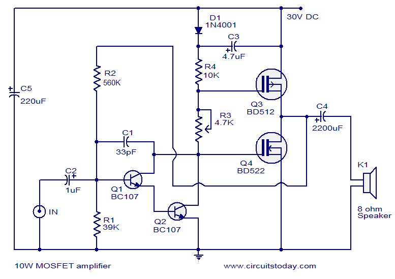
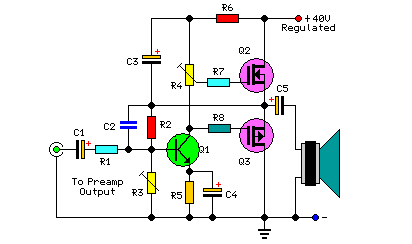
In summary, this audio amplifier circuit is a robust design that demonstrates effective use of MOSFET technology to achieve significant audio output with minimal components. The careful arrangement of stages and the use of feedback mechanisms contribute to its satisfactory performance in various audio applications.This article lists various types of audio amplifier circuits using Mosfet. We have tested all these circuits in our lab and we found all of them performing satisfactorily. The amplifier employs only one transistor and two MOSFETs and few resistors and capacitors in a shunt feedback scheme. This tiny circuit can can deliver a whopping 18Watts into 8 Ohm speaker or 30W into a 4 Ohm speaker. To get such a good performance and stability out of few components, a high quality well regulated DC power supply is necessary. This is very essential for reducing noise and getting a constant output power on varying loads. A good DC voltage regulator able of providing more than 2 Amps @ 40V can be used. You can expect such a power supply design very soon here in the power supply section. Assemble the board on a good quality PCB. Use a preamplifier board with tone control prior to this amplifier to get better performance. If you don`t want, then no problem because this amplifier circuit has enough punch with in it. The diagram shown here is of a 10W MOSFET audio amplifier circuit that requires only a single supply.
Single rail supply is seldom used in Class-B power amplifiers. Anyway, for low power applications like this it`s quite fine. Actually I got this circuit from an old cassette player that is still working and I am publishing it as it is. The powers MOSFETs BD512 and BD522 are obsolete now and so you may use any other matching power MOSFETS instead of them.
Transistors Q1 and Q2 is wired as a Darlington pair works as the preamplifier. Preset R3 controls the quiescent current while R2 provides feedback. Output is coupled to speaker through capacitor C4. Capacitor C5 is the power supply filter and C2 is the input DC decoupling capacitor. The first stage of the amplifier is a differential amplifier based on transistors Q1 and Q2. Capacitor C8 is the input DC decoupler, R1 limits input current and capacitor C1 bypasses unwanted high frequencies. The second stage is the driver stage consisting of transistors Q3 and Q4. Output stage is a complementary push pull stage based on MOSFETs IRF530 and IRF9530. Output is coupled the speaker using the inductor L1. Network comprising of R15 and C5 is meant for noise reduction. Capacitors C6 and C7 are power supply filters. Preset R6 is meant for adjusting the quiescent current. 🔗 External reference
Related Circuits
This page investigates a simple PA for 50MHz. This power amplifier will boost a low-level signal about 10-20mW to over 100mW. The power consumption will yet be quite low. At the bottom of this page, a complete transmitter based...
Headphone listening can be technically superior because it eliminates room reflections and allows for an intimate connection between the transducer and the ear, requiring only minimal power. This low power requirement enables transducers to operate at a fraction of...
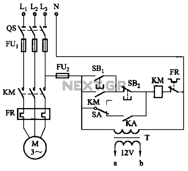
The circuit illustrated in Figure 3-81 employs a transistor delay circuit to facilitate start-stop cycle control. It can operate in both manual and automatic modes. The circuit is primarily governed by the motor run time circuit, which includes transistors...
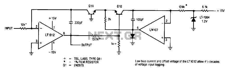
This simple logarithmic amplifier circuit uses the LT1012, which has a low bias current that allows for 4.5 decades of voltage input logging. Additionally, transistors that can be used in this circuit include the 2N2979. The logarithmic amplifier circuit designed...
This project includes a preamplifier, tone controls, a regulated DC power supply, and delivers 18 watts into an 8-ohm load and 30 watts into a 4-ohm load. The circuit design comprises several key components that work together to create...
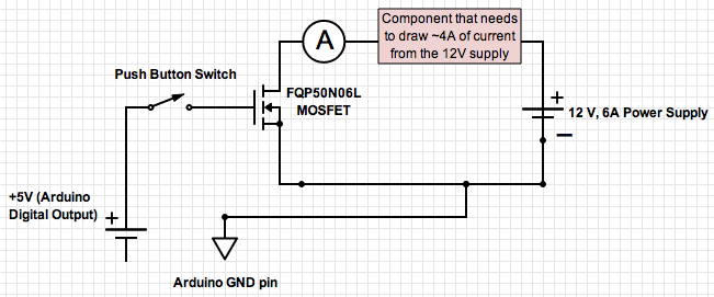
If the ground of the Arduino is disconnected from the negative terminal of the power supply, current flows through the MOSFET, even when the switch is not closed. In an electronic circuit involving an Arduino and a MOSFET, maintaining a...