
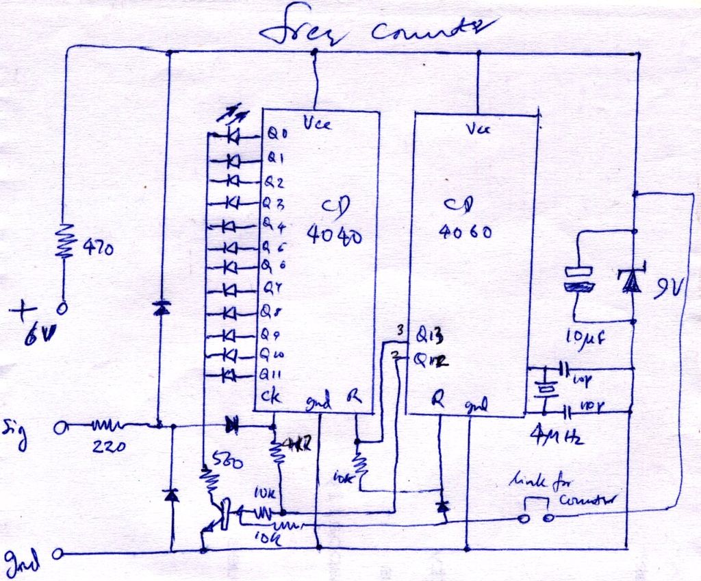
1750M Transverter Circuit
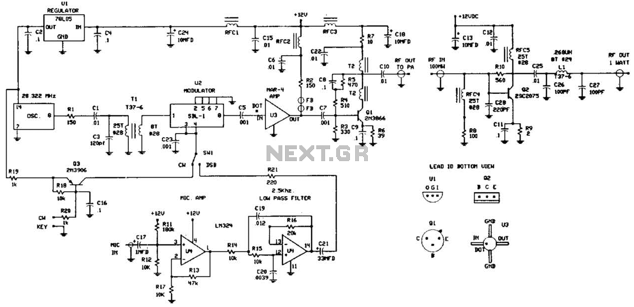
The circuit is designed to facilitate amateur radio communication within the specified frequency band while adhering to regulatory power limits. The receiving converter is crucial for capturing signals in the lower frequency range and converting them to a more manageable frequency for processing. This allows for effective demodulation and audio output, enabling clear reception of incoming signals.
The transmitting converter is responsible for taking the signals from the 80-meter band and translating them down into the 160 to 190 kHz range. This conversion process is essential for ensuring that the transmitted signals fall within the legal operating frequency range, allowing for seamless communication without interference.
The power supply requirement of 12 to 24 V provides flexibility in the choice of power sources, accommodating both portable and stationary setups. This versatility is beneficial for amateur radio operators who may wish to operate in different environments or under varying conditions.
Overall, the circuit presents a practical solution for amateur radio enthusiasts looking to explore the lower frequency bands, providing a robust platform for experimentation and communication in the specified frequency range. This circuit was described in a recent edition of an amateur radio magazine. It allows operation in the 160- to 190-kHz band with up to 1 W (license free) in any mode (CW/SSB/FM, etc.) It consists of a receiving converter for 5 kHz to 450 kHz and a transmitting converter to convert the 3.66- to 3.69-MHz (80 meter) range to 160 to 190 kHz. A 12- to 24-V power supply can be used. 🔗 External reference
Related Circuits
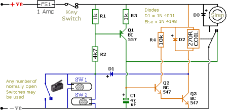
The schematic illustrates a Simple Motorcycle Alarm Circuit Diagram created by Ron J. It incorporates micro-switches to safeguard removable panels and... The Simple Motorcycle Alarm Circuit Diagram is designed to enhance the security of motorcycles by utilizing a series of...

This sound-activated switch allows for sound control, which can be beneficial not only for robotic applications but also for home automation. The sound-activated switch operates by detecting specific sound frequencies or patterns, enabling the user to control various devices or...
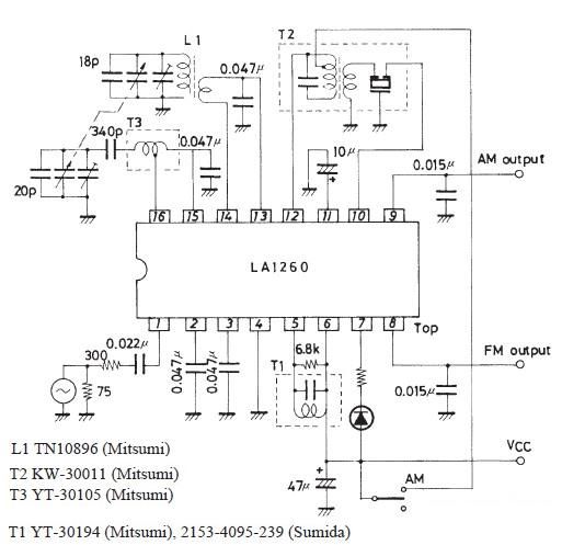
This FM IF MW radio receiver circuit schematic utilizes the LA1260 integrated circuit (IC), which is suitable for AM and FM radio receiver electronic projects. The LA1260 incorporates numerous functions and features essential for radio receiver applications, including a...
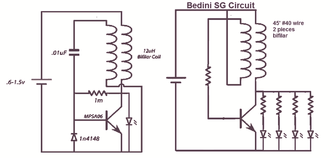
It would be beneficial to obtain schematics of the Joule Thief and Bedini oscillator circuit connections. This is an area that has not been previously explored. The schematic on the left was sourced from the Energetic Forum, while the...
The construction is nearly complete, and a circuit diagram has been created. The design has been finalized and documented on paper. The circuit diagram represents a critical stage in the development of an electronic project, serving as a blueprint for...
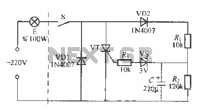
An incandescent lamp operates with a two-wire connection and features a life extension open circuit. It has a longer warm-up time compared to other types of lamps, resulting in a significant delay before illumination. Upon closing the switch, a...
Warning: include(partials/cookie-banner.php): Failed to open stream: Permission denied in /var/www/html/nextgr/view-circuit.php on line 713
Warning: include(): Failed opening 'partials/cookie-banner.php' for inclusion (include_path='.:/usr/share/php') in /var/www/html/nextgr/view-circuit.php on line 713