
MOSFET Power Amplifier

The described MOSFET power amplifier circuit utilizes two complementary MOSFETs, which are arranged in a push-pull configuration to efficiently amplify audio signals. The circuit is designed to deliver a power output of 20 watts into an 8-ohm load, making it suitable for various audio amplification applications.
In this configuration, one MOSFET is responsible for amplifying the positive half of the input signal, while the other amplifies the negative half. This complementary operation ensures that the output signal closely follows the input waveform, resulting in minimal distortion and improved linearity.
Key components of the circuit include the two complementary MOSFETs, typically an N-channel and a P-channel device. The choice of MOSFETs is crucial, as they must be able to handle the required voltage and current levels while maintaining low on-resistance to minimize power loss. Additional components may include biasing resistors to set the operating point of the MOSFETs, coupling capacitors to block DC offsets, and feedback components to stabilize the amplifier's gain and frequency response.
The power supply for the amplifier must be capable of providing sufficient voltage and current to drive the output stage effectively. A well-designed power supply will also include filtering capacitors to reduce ripple and noise, ensuring a clean power source for the amplifier.
Thermal management is another important aspect of the design, as the MOSFETs will generate heat during operation. Adequate heatsinking must be provided to dissipate this heat and prevent thermal runaway conditions that could damage the devices.
Overall, this MOSFET power amplifier circuit represents a robust solution for audio amplification, leveraging the advantages of complementary MOSFET technology to achieve high efficiency and performance.MOSFET Power Amplifier Circuit diagrams Two complementary MOSFETs are used to deliver 20W into 8?. PARTS.. 🔗 External reference
Related Circuits
This circuit utilizes the TA7222AP to amplify audio signals. The cost is only $0.99, and it can provide 5.8 watts with muting control. The power supply can be in the range of 8-12 VDC, making it suitable for applications...
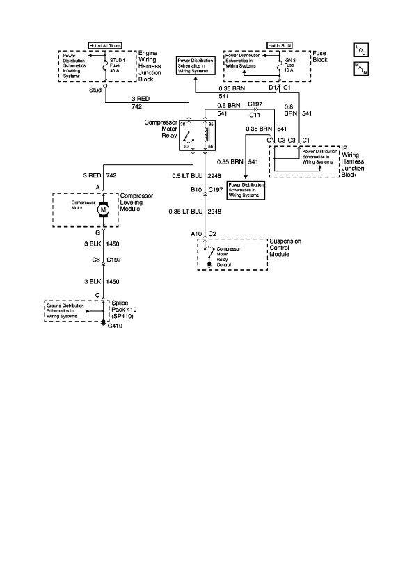
The physical location of the compressor relay is needed, as well as instructions on how to test the pressure sensor on the plastic tank of the compressor assembly. The exact location of the relay has not been confirmed, but...
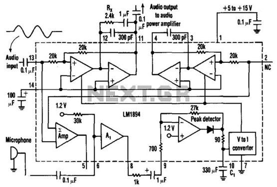
This single-chip circuit adjusts its audio gain according to the ambient noise picked up by the microphone. When operating in a quiet environment, the audio output is quiet, while a noisy environment results in a louder audio output. Audio...
This technique eliminates the need for an additional cable to power the FM antenna amplifier. The RF signal and the DC current that supplies the amplifier utilize the same cable simultaneously. An FM antenna booster circuit diagram can be...
A 5-minute circuit can continue to operate during a power outage, providing protection for the refrigerator. The refrigerator power protection circuit, designated as 1136, includes a power transformer that converts 220V voltage through a rectifier bridge (VD1). This setup...

Designed for self-powered 8, 4 & 2 Ohm loudspeakers. This amplifier was designed to be self-contained in a small loudspeaker box. It can be fed by Walkman, Mini-Disc, iPod and CD players, computers and similar devices fitted with line...