
The 2N5109 Amplifiers
The Progressive Communications Receiver circuit is designed to enhance signal processing capabilities in radio frequency applications. It incorporates a 2N5109 transistor as the primary amplification component, which is well-regarded for its performance in RF amplification. The circuit's architecture allows for efficient handling of intermediate frequency signals, making it suitable for various communication systems.
The use of T50-43 ferrite cores for the transformers is a critical design choice, as these cores provide optimal magnetic properties for the intended frequency range. The trifilar winding technique employed for the transformers aids in maintaining balanced impedance, which is crucial for minimizing signal loss and maintaining fidelity in the output signal.
The feedback mechanism implemented in this circuit is noteworthy. By utilizing both voltage and current feedback, the design effectively reduces intermodulation distortion, a common problem in RF amplifiers that can degrade signal quality. The transformers not only serve their primary function of impedance transformation but also contribute to the stability of the circuit, ensuring consistent performance across varying load conditions.
The circuit's input and output impedances are standardized at 50 ohms, which is a common requirement in RF systems, allowing for seamless integration with other components and systems without the need for additional matching networks. The compact nature of the design, along with the inclusion of a diode mixer and crystal filter, further enhances its utility in modern communications applications.
The mathematical analysis provided in the appendix of the original article offers valuable insights into the performance characteristics of the circuit, allowing engineers to understand its behavior under different operating conditions. This comprehensive approach to design and analysis makes the Progressive Communications Receiver a robust solution for high-frequency communication needs.This diagram comes from the Progressive Communications Receiver that is in most of the latest ARRL Handbooks. This amplifier is used anywhere an IF amplifier is needed. W6BKY has a receiver article at Hamradio-online that shows how to build this circuit on a universal printed circuit board.
Very compact and includes a diode mixer and crystal filte r. Check out The 2N5109 amplifier can be simulated using the Serenade SV program. Information on using the program and simulating the amplifier can be found at "Simulating Circuits and Systems with Serenade SV", by David Newkirk, W9VES, January 2001, QST, Page 37. This amplifier is used for the front-end RF amplifier. T50-43 ferrite cores are used instead of the Indiana General toroid cores noted in the text of the original article.
Transformers are trifilar wound. Input and output impedances are 50 ohms. This circuit is a modified version (cores only) of the one in Ham Radio, October 1976, Ulrich L. Rohde, "Optimum Design for High-Frequency Communications Receivers", Page 18. The circuit "uses voltage and current feedback to minimize intermodulation distortion, while the transformers act as impedance stabilizing devices. The cores recommended are F625-0-TC9 for 1. 5-230 MHz or F625-9-Q1 for the higher frequencies (made by Indiana General). " This amplifier was first published on October 1975, Ham Radio, "High Dynamic Range Receiver Input Stages", Page 26.
A mathematical analysis of this circuit is presented in the Appendix of this article (page 31). 🔗 External reference
Related Circuits
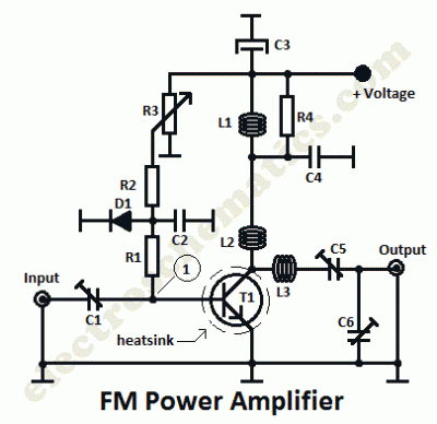
This is a 1 watt FM amplifier with a robust design that can be used to amplify an RF signal in the 88 to 108 MHz band. It is highly sensitive when utilizing quality RF power amplifier transistors, trimmers,...
The IRF820 MOSFET has a voltage rating of 500V; it should work well in preamp stages of most tube amps. The 100-ohm resistor is there to suppress H.F. oscillations. If the IRF820 is physically close to the 12AX7 plate,...
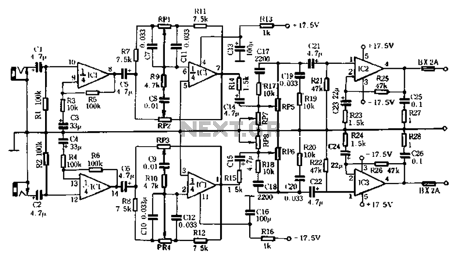
The circuit depicted in Figure 5-60 and Figure 6 utilizes an operational amplifier (op-amp) configured as a channel pre-amplifier to address the signal loss introduced by the tone control circuit. Additionally, another group of op-amps forms a channel-driven stage...
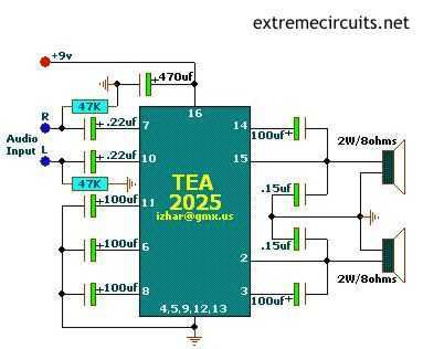
The above circuits are based on TEA2025, a monolithic integrated audio amplifier in a 16-pin plastic dual in-line package manufactured by UTC. The circuit has an internal thermal protector and is designed for portable cassette players and radios. It...
The circuit is a microphone amplifier designed for low impedance microphones, approximately 200 ohms. It operates with stabilized voltages ranging from 6 to 30 VDC. If the impedance adapter section with T1 is not constructed, the circuit can be...
It has been mentioned that the operational amplifier (op amp) in the second stage may be damaged. Confirmation is requested by testing the op amp in a buffer configuration or any simple configuration. This test is necessary to ascertain...
Warning: include(partials/cookie-banner.php): Failed to open stream: Permission denied in /var/www/html/nextgr/view-circuit.php on line 713
Warning: include(): Failed opening 'partials/cookie-banner.php' for inclusion (include_path='.:/usr/share/php') in /var/www/html/nextgr/view-circuit.php on line 713