
Softrock RX + Xtall V9.0 USB Control Stage
The Si570 is a programmable oscillator that can be used in various radio frequency applications. The integration of the Si570 with the RX board through a USB interface allows for precise frequency control, which is essential for digital signal processing (DSP) applications. The driver installation process is straightforward but must be executed with care to avoid communication issues between the software (Rocky) and the hardware (Si570).
Upon connecting the RX board to a USB port, the operating system will prompt for the driver location. It is important to ensure that the driver files are extracted correctly to facilitate a smooth installation. Once installed, the Si570 can be configured within the Rocky software environment, which is designed for software-defined radio (SDR) applications. The "Use Si570-USB" checkbox in the DSP settings enables the software to communicate with the Si570 chip, allowing for frequency adjustments and other functionalities.
The settings for "address" and "divider" are critical parameters that dictate the operating behavior of the Si570. Modifying these settings without proper understanding can lead to erratic performance and communication errors. The warning against using Rocky's frequency changing mechanism prematurely highlights the importance of ensuring that the LO stage is properly configured before attempting to set operational frequencies. The "error -5" message serves as a diagnostic tool, indicating that the software attempted to set an invalid frequency, emphasizing the need for careful configuration and adherence to the specified procedures.
In summary, the integration of the Si570 with the RX board through USB provides a powerful tool for frequency control in SDR applications, but it requires precise attention to detail during installation and configuration to avoid operational issues.The driver files are located in the Si570AVR-USB-Driver folder inside the zip. Extract them into a new directory, and connect the RX board`s USB cable to a USB port. When prompted for the driver location, navigate to the extracted files and let windows install the drivers. Once the driver is installed, enable the Si570 support in Rocky by ticking the "Use Si570-USB" check box in the Settings/DSP dialog. Do not change the "address" and "divider" settings. It is very important to follow the procedure below exactly. The USB interface and Rocky can interact in very strange fashion if you do not. Also, do not try to use Rocky`s frequency changing mechanism until after the LO stage. Rocky will issue an "error -5 message: Set frequency (28184000) failed: USB_control_msg error -5 signifying it tried to set the frequency to 4 times the default center frequency (7046000) in Rocky and did not receive any acknowledgement from the Si570 back through the USB Interface 🔗 External reference
Related Circuits
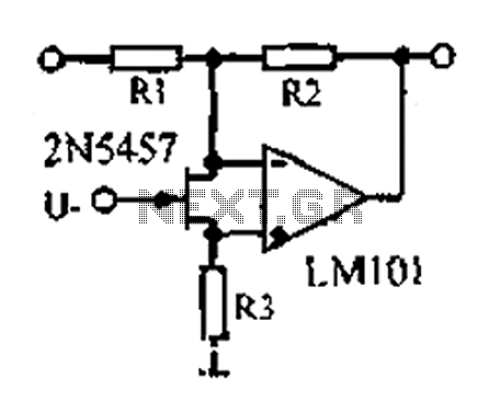
A 1.53 voltage-controlled gain amplifier (VGA) utilizes a FET connected between the two inputs of the operational amplifier (op-amp) as a voltage-controlled resistance. The resistance changes linearly with voltage and varies from several dozen square ohms, exhibiting excellent control...
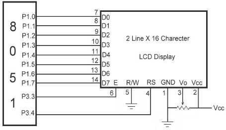
The link shows how to interface Alphanumeric LCD to 8051 Microcontroller. Liquid Crystal Display also called as LCD is very helpful in providing user interface as well as for debugging purpose. The most common type of LCD controller is...
A wooden table features numerous holes of varying diameters designed to accommodate optical fibers. Due to the size of the ceiling lamp (90 cm x 60 cm), it was not feasible to utilize a single bundle of fibers, resulting...
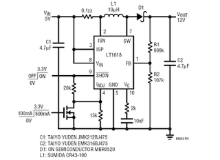
This is a 5V to 12V DC-DC step-up (boost) converter circuit designed specifically for USB-powered applications. A USB port has two current supply modes. Initially, it supplies a maximum of 100mA to the load before detecting the connected device....
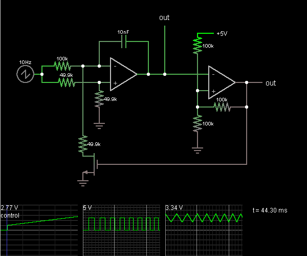
This circuit is a voltage-controlled oscillator, which is an oscillator whose frequency is determined by a control voltage. A 10 Hz sawtooth oscillator provides the control voltage in this case; this causes the frequency to rise slowly until it...
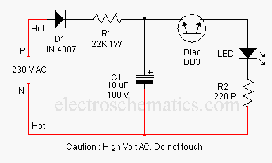
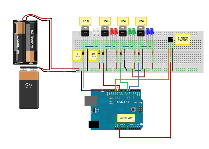
This concept involves generating a flashing light from an LED using alternating current (AC). The circuit is a simple method for flashing one or more LEDs from high voltage direct current (DC) obtained from mains electricity. It can serve...