
Shared antenna amplifier power since the controller circuit diagram
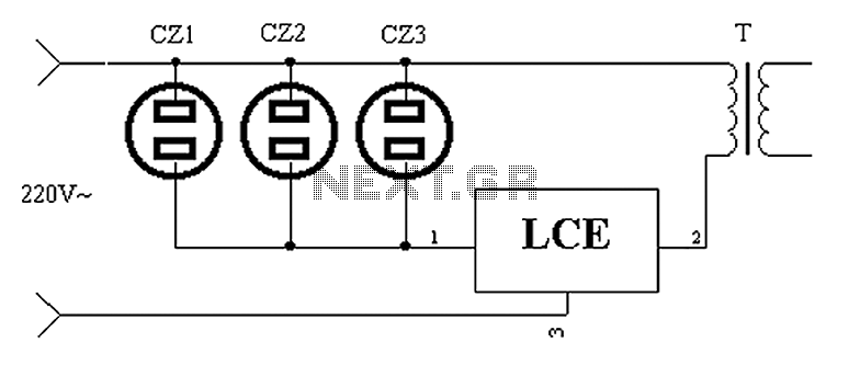
The circuit design incorporates a shared TV antenna amplifier that enhances signal reception for multiple televisions. The amplifier is powered through a user-isolated switch, which prevents it from drawing power unnecessarily when not in use. The LCE module serves as an intelligent control mechanism that monitors the power status of the connected televisions.
When a television is connected to one of the designated sockets (CZ1, CZ2, CZ3, etc.), the LCE module detects the load and automatically closes the power switch for the shared antenna amplifier. This action ensures that the amplifier is only powered when at least one television is in operation, thereby reducing energy wastage.
The LCE module can be designed to accommodate additional sockets, allowing for flexibility in installation while remaining within the power limits of the LCE unit. This arrangement not only optimizes energy consumption but also simplifies user experience by eliminating the need for manual switching. The overall circuit provides an efficient solution for households with multiple televisions, enhancing both convenience and energy efficiency.Application circuit works the device as shown below. Generally shared TV antenna amplifier and power switch user is isolated. Sometimes no one can work the TV, the antenna ampl ifier is still powered on, the power consumed in vain. Other times, it may have more than one television program is being received, and shared antenna amplifier power switch is not closed, of course, not so good reception. Using LCE module can be easily controlled automatically. When the socket CZ1 TV used, CZ2, CZ3 (of course, can also be designed to install more electrical outlets, so long as the LCE power allow) any one inserted TV power switch is closed, the shared antenna amplifier the power supply automatically.
Then they will not waste energy, without affecting the TV user, and does not require special management.
Related Circuits
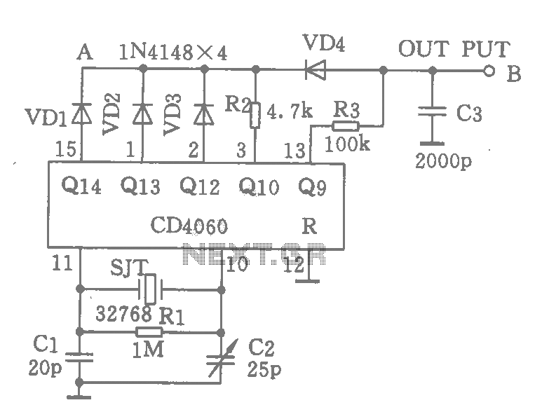
A CD4060 integrated circuit, combined with a 32,768 Hz crystal oscillator, is utilized to create a highly accurate clock source that generates 60 pulses per second. The operation is based on the division of the 32,768 Hz pulse output...
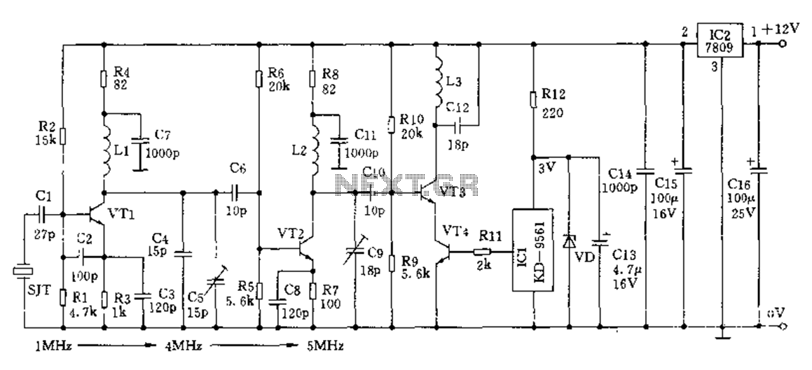
The crystal frequency stabilization of a frequency modulation circuit is illustrated below. The frequency modulation (FM) circuit utilizes crystal frequency stabilization to ensure precise frequency control and stability. This process involves the use of a quartz crystal oscillator, which...
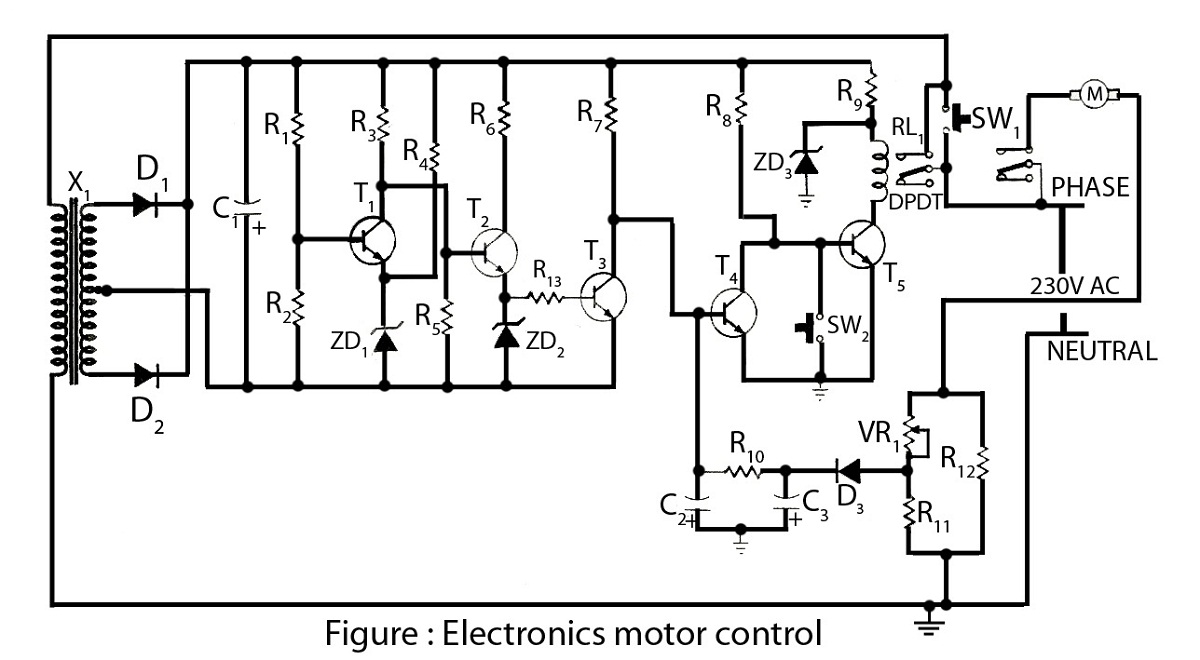
Electronics motor control is a simple circuit made without an integrated circuit (IC). It involves the electronic control of an AC motor and includes a circuit diagram along with a description of the electronics motor controller. The electronics motor control...
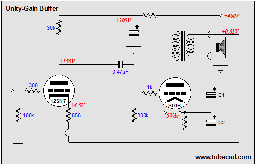
The solid-state, unity-gain power buffer is a well-known concept, but corresponding tube equivalents are less common. While super cathode followers, which are complex and augmented cathode followers with a gain of 0.99, have a long history with various designs...
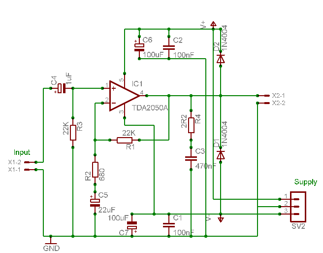
A careful examination of the amplifier photos reveals that the heatsink on the HY60 near-clone built using the TDA2050A is slightly shorter than that of the original HY60s. This unit is positioned at the rear of the amplifier, creating...
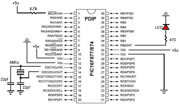
PIC development/testing board. This is a PCB design for a basic PIC16F877 development board. All that is required is a 4 MHz crystal, two 22 pF capacitors, and one 4.7 kΩ resistor. The PIC16F877 development board is designed to facilitate...
Warning: include(partials/cookie-banner.php): Failed to open stream: Permission denied in /var/www/html/nextgr/view-circuit.php on line 713
Warning: include(): Failed opening 'partials/cookie-banner.php' for inclusion (include_path='.:/usr/share/php') in /var/www/html/nextgr/view-circuit.php on line 713