
Single-speed motor excitation from the electrical braking circuit
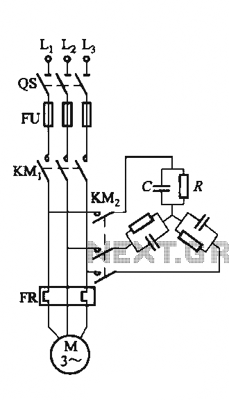
The circuit design in Figure 3-151 is essential for optimizing the performance of Y-connected motors, which are commonly used in industrial applications. The shaped capacitor configuration allows for a more compact design, reducing the overall footprint of the motor system while maintaining efficiency. This configuration is particularly advantageous when space constraints are present.
In the context of the Y-connected capacitor banks, these components are critical for power factor correction and voltage stabilization in the motor system. The Y-connection facilitates balanced loading across the three phases, which is essential for the proper operation of three-phase motors. The capacitor banks help to mitigate reactive power demands, thereby improving the overall efficiency of the motor.
The requirement for a higher voltage rating of 600V or more for the shaped capacitors indicates that these components must be carefully selected to withstand the operational conditions without risk of failure. The selection criteria outlined in Table 3-2 provide guidance on choosing the appropriate capacitors and resistors based on the specific power ratings of the motors in use. This ensures that the circuit operates within safe parameters while delivering optimal performance.
Overall, the design and implementation of the capacitor banks in the configurations shown are crucial for enhancing the operational efficiency and reliability of Y-connected motors in various applications.Circuit shown in Figure 3-151. Figure 3-151 (a) of the capacitor banks connected into shape, it applies to shaped or Y-connected motor; Fig. 3-151 (b) of the Y-connected capacitor banks, it applies to Y-connected motor . Shaped capacitor using connection, the required electrical smaller capacity, but requires higher voltage value (600V or more). Different power motors, C and R selection Table 3-2.
Related Circuits
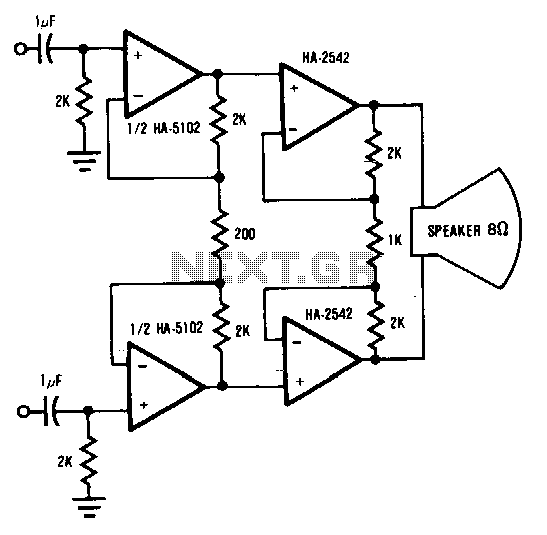
This circuit demonstrates a method to enhance the power capability of a drive system for audio speakers. Two HA-2542 amplifiers are utilized to operate on half cycles only, significantly increasing their power handling capacity. Bridging the speaker, as illustrated,...
This circuit diagram for a 12V inverter is straightforward to construct, utilizing inexpensive components that many electronics hobbyists may already possess. While it is feasible to design a more powerful circuit, the complexity associated with handling high currents on...
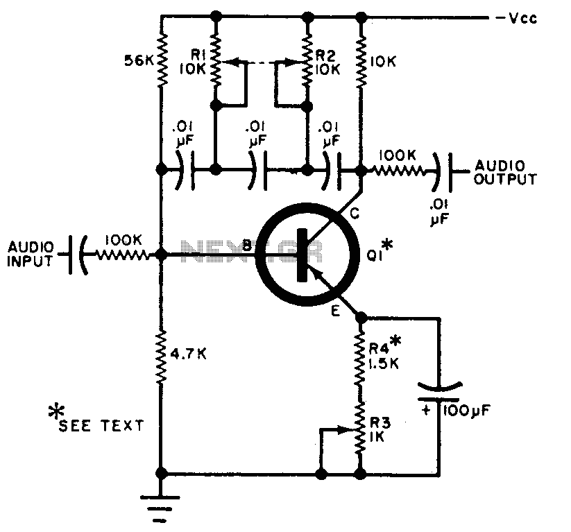
The circuit can be selectively tuned to two closely related tones. The selective frequency is determined by the values of the feedback circuit connected to the collector and base of Q1, which includes capacitors and resistors. When the specified...
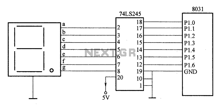
After the SCM execution, the Pl output port connects to the bidirectional input of 74LS245 driver chips. This driver operates during each phase of digital control, based on the information from the Pl port. The purpose is to convert...
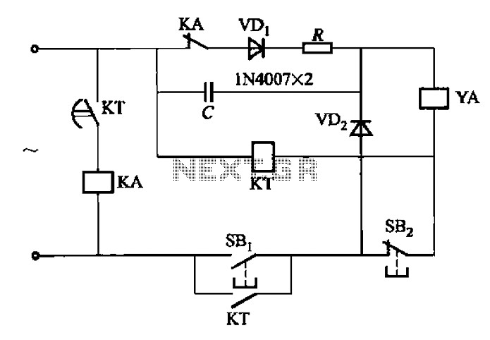
AC solenoid DC circuit operation operates similarly to a DC contactor circuit, but the AC solenoid pull circuit is illustrated in the provided figure. The capacitance C is generally between 1-10 microfarads (µF), with a minimum of 20 microfarads...
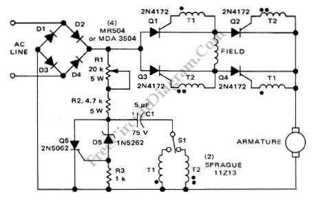
This is a motor controller circuit that controls the speed and direction of series-wound motors. This circuit employs silicon controlled rectifiers (SCR). The motor controller circuit is designed to manage both the speed and direction of series-wound motors, which are...