
Mosquito-repelling circuit

The 555 oscillator circuit operates in astable mode, generating a continuous square wave output. The frequency of oscillation is primarily determined by two resistors (R1 and R2) and a capacitor (C1). The formula for calculating the frequency (f) of the output waveform is given by:
f = 1.44 / ((R1 + 2R2) * C1)
By varying the resistance of R2, the duty cycle and frequency of the output signal can be adjusted. Lowering R2 increases the frequency, while increasing R2 decreases the frequency. This flexibility allows for a wide range of output frequencies, making the 555 timer a versatile component in various applications.
For optimal performance, especially at higher frequencies around 20 kHz, it is advisable to select a high-quality miniature speaker with a suitable frequency response. The speaker should be capable of accurately reproducing the desired frequencies without distortion. Additionally, the power rating of the speaker should match the output capabilities of the 555 circuit to avoid damage to the speaker or the circuit itself.
In practical applications, the circuit can be powered by a DC voltage source, typically ranging from 5V to 15V, depending on the specifications of the 555 timer used. Proper decoupling capacitors should be employed near the power supply pins of the IC to minimize noise and ensure stable operation. The output can be connected directly to the miniature speaker, or through a transistor amplifier stage for increased power handling, depending on the requirements of the application.In the 555 oscillator circuit, adjusting R2 will provide output frequencies from below 200 Hz to above 62 kHz Use a good quality miniature speaker so that it will produce frequencies on the order of 20 kHz.
Related Circuits
The electric car remote control circuit diagram enables the model car to move forward and backward, as well as turn left and right. It is simple and easy to operate. The radio remote control receiver demodulation circuit utilizes TWH9238...
The filter consisting of resistors R1, R2, and capacitor C1 integrates the PWM waveform. The purpose of the operational amplifier appears to be that of a non-inverting amplifier, with the gain determined by resistors R6 and R7. However, the...
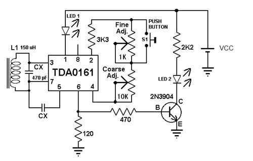
These metal detector circuit diagram is based on the TDA0161 monolithic integrated circuit, designed for metallic body detection by detecting the variations in high frequency Eddy current losses. For detecting metals, TDA0161 require an external LC tuned circuit. Output signal...

This simple circuit can create an 18 LED flasher to decorate a Christmas tree. The white, blue, and red LEDs flash at different rates to provide a colorful display. It is a light-sensitive circuit, automatically activating in the evening...
This is a luminous flux test circuit that utilizes optical resistors. In the circuit, the optical resistor RG forms a bridge with resistors RP1, RP2, R1, and R2. RP1 is employed to balance the bridge, while RP2 is used...
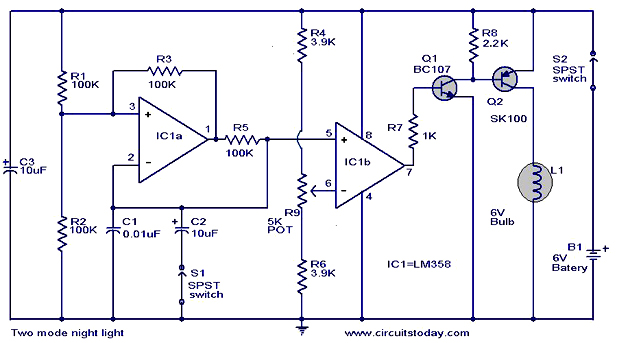
The operation and circuit diagram of a two-mode night light circuit are provided below. The two-mode night light circuit is designed to operate in two distinct lighting modes, typically offering a choice between a standard brightness setting and a dimmer,...