
Two mode night light circuit - WorkingCircuit DIagram

The two-mode night light circuit is designed to operate in two distinct lighting modes, typically offering a choice between a standard brightness setting and a dimmer, energy-saving mode. This circuit can be particularly useful in environments such as bedrooms or hallways, where a soft light is preferred during nighttime hours.
The core components of the circuit include a light-emitting diode (LED) for illumination, a resistor to limit the current flowing through the LED, and a switch mechanism that allows the user to toggle between the two modes. Additionally, a transistor may be used to amplify the control signal from the switch, enabling the circuit to handle the different brightness levels effectively.
In the standard mode, the LED is powered directly, providing maximum brightness. In the dim mode, the circuit could utilize a resistor in series with the LED to reduce the current, resulting in a lower light output. Alternatively, a pulse-width modulation (PWM) approach could be employed to control the brightness dynamically, allowing for a more efficient power usage.
The schematic diagram typically illustrates the arrangement of these components, with clear indications of the power supply connections, the orientation of the LED, and the placement of the switch. Proper attention to the values of the resistors and the specifications of the LED is crucial to ensure optimal performance and longevity of the circuit.
In summary, the two-mode night light circuit is a practical solution for providing adjustable lighting in low-light environments, combining functionality with energy efficiency.The working and circuit diagram of a two mode night light circuit is given below.. 🔗 External reference
Related Circuits

This is an AC-powered LED flasher that can drive two high-bright LEDs directly from the power obtained from the AC lines. The high-bright LED flasher can be... The AC-powered LED flasher circuit is designed to illuminate two high-bright LEDs using...
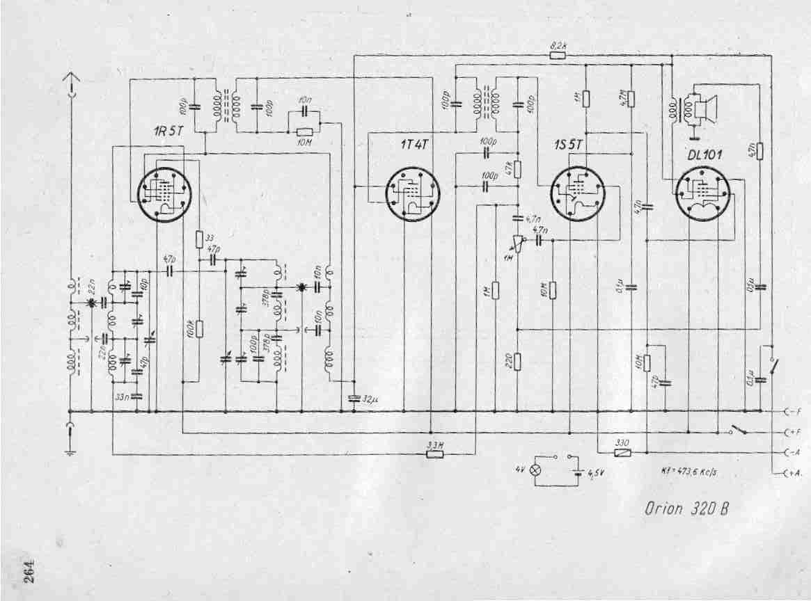
Create a repository of circuits and service data for vintage valve and transistor radios. While many resources are available online, they often come at a cost. The intention is to share circuits and manuals with others rather than profit...
This project involves a straightforward soil moisture detection circuit that utilizes only four components and operates with a 3-volt battery. The circuit is designed to identify the presence of moisture in the soil of any plant and activate an...

This example describes a wireless remote control switch featuring reliable operation and practical characteristics, capable of remotely controlling a 6-channel device within a 6-meter range for household electricity. The wireless remote control switch circuit consists of a wireless transmitter...
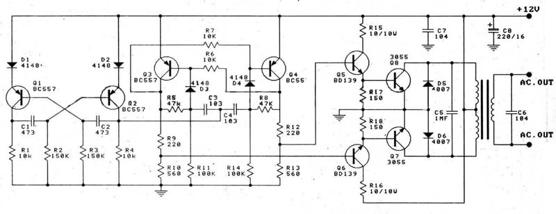
A 12V car battery is recommended as the input for this circuit, utilizing the 2N3055 transistor as the amplifier. This configuration can deliver a power output of up to 100W, making it suitable for use in battery chargers, emergency...
The welder no-load power saver circuit consists of a current detection control circuit and a power saving control circuit, as illustrated in the accompanying chart. The current detection control circuit includes a current transformer (TA), a bridge rectifier (UR),...