
Metal detector circuit with TDA0161

Output signal is determined by supply current changes. Independent of supply voltage, this current is high or low according to the presence or the absence of a close metallic object. This metal detector circuit use two LEDs, which offer an visual indication of presence or absence at a metals, around the coil. To adjust the circuit you need to make sure there is no metal near the coil and then set the fine adjustment to a "Mid position". After that you need to adjust the course adjustment to turn on the LED and, adjust the fine adjustment to turn off the LED. More: This detector electronic circuit operates over a wide range input voltage of 4 -35 volts. If you want you can use other values for the Cx capacitor and for L1 inductor (changing this value will affect the frequency oscillation and the detection range).
The metal detector circuit utilizing the TDA0161 integrated circuit is designed specifically for the detection of metallic objects by exploiting the principles of Eddy current loss. The TDA0161 is a monolithic IC that requires an external LC tuned circuit to function effectively. This tuned circuit is critical as it determines the operational frequency of the detector, which in turn influences the sensitivity and range of metal detection.
When a metallic object is brought close to the coil, the high-frequency oscillations generated by the LC circuit are influenced, resulting in variations in the supply current. These variations are independent of the supply voltage, allowing the circuit to maintain functionality across a wide range of input voltages, specifically from 4 to 35 volts. The output signal, which indicates the presence or absence of metal, is visually represented by two LEDs integrated into the circuit. The first LED lights up when metal is detected, while the second LED indicates when no metal is present.
For optimal performance, the circuit requires careful calibration. Initially, it is essential to ensure that no metallic objects are within proximity of the coil. The fine adjustment should be set to a mid-position, followed by the course adjustment, which is used to activate the LED. Fine-tuning is then performed to deactivate the LED, ensuring sensitivity is correctly calibrated.
The choice of components, particularly the values of the capacitor (Cx) and inductor (L1), plays a significant role in the circuit’s performance. Altering these values will directly impact the frequency oscillation characteristics and the effective detection range of the device, allowing for customization based on specific application requirements. This flexibility makes the TDA0161-based metal detector suitable for various environments and detection scenarios.These metal detector circuit diagram is based on the TDA0161 monolithic integrated circuit , designed for metallic body detection by detecting the variations in high frequency Eddy current losses. For detecting metals , TDA0161 require an external LC tuned circuit . Output signal is determined by supply current changes. Independent of supply voltage, this current is high or low according to the presence or the absence of a close metallic object.
This metal detector circuit use two LEDs , which offer an visual indication of presence or absence at a metals ,around the coil . To adjust the circuit you need to make sure there is no metal near the coil and then set the fine adjustment to a "Mid position".
After that you need to adjust the course adjustment to turn on the LED and , adjust the fine adjustment to turn off the LED. This detector electronic circuit operates over a wide range input voltage of 4 -35 volts . If you want you can use other values for the Cx capacitor and for L1 inductor ( changing this value will affect the frequency oscillation and the detection range ) . 🔗 External reference
Related Circuits
This circuit is designed to indicate through a flashing LED when room noise exceeds a predetermined threshold, selectable from three fixed levels: 50, 70, and 85 dB. Two operational amplifiers (op-amps) are utilized to amplify the sound captured by...
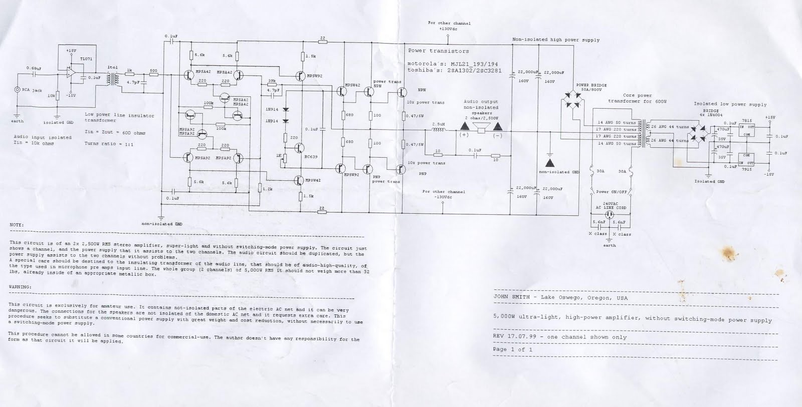
This device is a 2x2, 500W RMS stereo amplifier, designed to be super-lightweight and equipped with a switching-mode power supply. The device features a single channel display and specifies the power output it provides to both channels. The audio...
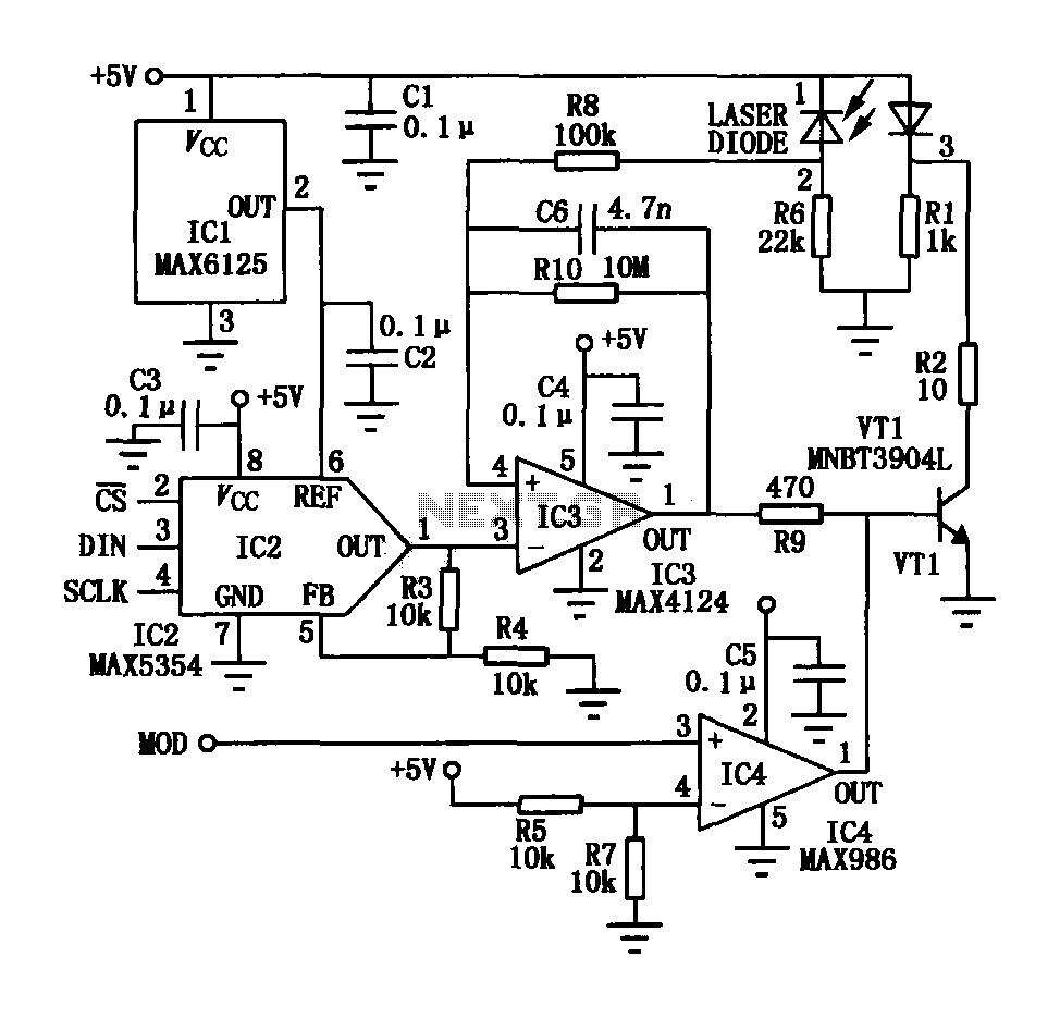
The laser tube drive circuit typically incorporates a photodiode that generates a laser beam proportional to the intensity (optical power) of the current. However, this type of photocell is generally slow and unable to track modulation effectively, particularly for...

Characterized by a steady flow of power when the power supply voltage fluctuates or the load changes, this circuit maintains a constant load current. The output current of the circuit is illustrated in Figure 4A. When the load varies...
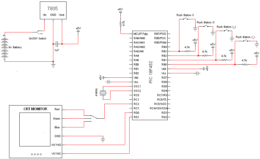
Very few electronic components are required for this project, as the PIC Microcontroller serves as the primary processing unit. The essential components include buttons, switches, and a power circuit, which are straightforward forms of input/output, facilitating an easier understanding...
This document presents plans for a simple ground plane antenna that is effective in the FM band (88-108 MHz). It is constructed from a small plastic disk. The 6 x 6 loop antenna, designed by Graham Maynard, is highlighted...