
Motion Control Sensor Interface
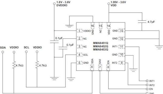
The circuit design encompasses a modular architecture, allowing for the integration of various components while ensuring efficient data flow. The ProSpeckz IIK microcontroller serves as the central processing unit, managing the Zigbee radio communication and interfacing with the MMA8451Q accelerometer. The accelerometer's output is processed through an I2C interface, which simplifies communication and reduces pin count. The circuit layout includes power supply management to ensure stable operation of all components, with decoupling capacitors placed near power pins to filter out noise.
The PCB design follows best practices for signal integrity, with careful routing of high-frequency signals to minimize interference. Ground planes are utilized to provide a low-resistance return path, enhancing the overall performance of the system. The Zigbee radio module is positioned to optimize antenna performance, ensuring reliable wireless communication over the intended range.
In terms of software, the firmware running on the ProSpeckz IIK is optimized for real-time data acquisition and transmission. It handles the collection of accelerometer data, formats it into the defined packet structure, and manages the radio transmission process. Error-checking algorithms are integrated into the data transmission routine, allowing for the identification and retransmission of corrupted packets, thus enhancing the reliability of data communication.
Overall, this comprehensive design emphasizes robustness, efficiency, and scalability, enabling future enhancements and adaptations as requirements evolve.My task for the system was to implement and program all the hardware devices and make data available to the receiver program running on the PC. This includes the configuration of all Prospeckz devices and implementing protocols for radio transmissions communication back to PC.
I was also tasked with setting up the accelerometer chip(s) for data ga thering. To do this, I split the problem into several requirements: The wireless communications between hardware devices were initially required to support a single transmitter, however this requirement was amended in later stages of system development to support receiving data from multiple transmitters with minimal losses. To define the format of data transferred from receiver to PC, I worked closely with Li to create a compact and efficient format that conforms to the standards of my implementation and the PC processor that he worked on.
- Design the circuit peripherals around the chips and mount them on protoboards for testing, later switching to small PCBs to integrate with transmitters compactly Initially the group had an idea to also incorporate a gyroscope into the hardware implementation to increase the system`s capabilities, however no devices were available and in the end only an accelerometer proved to be sufficient. In response to the requirements above, I tackled each task individually, making sure the implementation is robust before moving on to the next stage.
I first implemented the radio communications between transmitter and receiver, using test programs on the Prospeckz such as the Cycling Led example in the Prospeckz Guide to verify by design. The ProSpeckz IIK (Programmable Speck using Zigbee Radio) was used extensively in this project, as it acted as the main microcontroller for all hardware behavior.
Some of its notable peripherals include an RGB LED, A Zigbee Radio Chip with 2. 4GHz antenna, one reset switch and one programmable switch, and two 8-bit ports for interfacing with other components. The PSoC CY8C29666-24LFXI is housed within the ProSpeckz as the main programmable component and microcontroller.
All these models incorporate the same basic features: 3-axis measurements, support for I2C master-slave communication, good resolution range and low-power operation. It was a draw as to which device to choose, so I ultimately settled for the MMA8451Q accelerometer due to higher availability in the university and because it was easier to integrate with the rest of the system as a breakout board.
After consulting the accelerometer datasheet and discussing with the group, it was decided that for the wireless communication, a packet size of 8 bytes is compact enough while being sufficient. This is due to the fact that the accelerometer provides data with 14 bit resolution, meaning it needs 2 bytes to store the acceleration measurement from each axis; these 2 bytes are denoted as MSB (most significant bits) and LSB (least significant bits).
A total of 3 axes amount to 6 bytes of raw data, to be added together in the packet along with the device`s ID (for multi-device support). The packet format is shown below, with each colored box denoting 1 byte (8 bits): Note that the low-level code controlling the radio appends an additional byte at the end of each packet which contains the packet`s length; this is not shown in the diagram above.
We left the 8th byte empty in case it was ever needed for additional transfers; Once the group was certain the data transferred is sufficient, the realistic payload of the radio communication was 7 bytes per packet (without overhead bytes). Additionally, some error-checking had to be performed on the radio communication in order to determine corrupted/incomplete/invalid packets.
Deciding that the microcontroller is better suited dedicating itself to the control aspects of the hardware, we build the error-checking into the backend processor executing on the PC. Once packet 🔗 External reference
Related Circuits
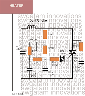
Controlling heaters rated up to 1500 watts requires stringent specifications for the controlling unit to ensure safe and effective operation. The introduction of advanced snubber-less Triacs and Diacs has made it relatively easier to implement heater controllers at high...

While developing an infrared (IR) extender circuit, a method was needed to measure the relative intensities of various infrared light sources. This circuit is the outcome of that research. A photodiode, specifically the SFH2030, is utilized as the infrared...
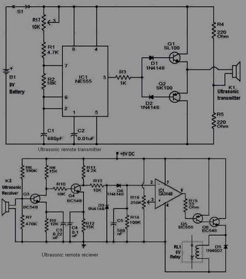
This circuit is straightforward and well-defined. The transmitter operates at 9 volts, while the receiver circuit functions at 5 volts. The transmitter utilizes a 555 timer and two SL100 transistors to perform its function. The receiver incorporates a small...
Dew (condensed moisture) adversely affects the normal performance of sensitive electronic devices. A low-cost circuit described here can be used to switch off any gadget automatically in case of excessive humidity. At the heart of the circuit is an...
This DIY magnetic field sensor circuit is straightforward and capable of detecting both static magnetic fields and those that vary at audio frequencies. The unit is designed to be user-friendly and efficient. The magnetic field sensor circuit typically employs a...
The circuit operates based on a desired temperature setting. It can be utilized for various applications, such as turning on a fan at a specified temperature or activating an emergency temperature alarm. The power supply for the circuit can...
Warning: include(partials/cookie-banner.php): Failed to open stream: Permission denied in /var/www/html/nextgr/view-circuit.php on line 713
Warning: include(): Failed opening 'partials/cookie-banner.php' for inclusion (include_path='.:/usr/share/php') in /var/www/html/nextgr/view-circuit.php on line 713