
Dew sensor circuit

The described circuit utilizes a dew sensor to monitor humidity levels and activate a switching mechanism when moisture levels become excessive. The dew sensor operates on the principle that its resistance varies significantly with humidity; under normal conditions, the resistance is approximately 1 kΩ, resulting in a low voltage at the non-inverting terminal of the LM358N op-amp. The op-amp is configured as a comparator, where the non-inverting terminal (pin 3) is connected to the dew sensor, and the inverting terminal (pin 2) is set at a reference voltage.
When the humidity rises above 80%, the resistance of the dew sensor increases, causing the voltage at the non-inverting terminal to exceed that of the inverting terminal. This condition changes the output state of the op-amp from low to high, which activates the internal LED of the opto-coupler. The opto-coupler serves as an interface to control other electronic devices, effectively allowing the circuit to disconnect or switch off the device in response to high humidity.
Additionally, LED1 provides a visual indication of the circuit's activation state, alerting users to the presence of excessive humidity. The power supply section of the circuit, which includes diode D2, resistors R5 and R6, and capacitor C1, is designed to generate a low-voltage supply from the main power source, eliminating the need for a larger step-down transformer. This design choice enhances the overall compactness and cost-effectiveness of the circuit while ensuring reliable operation in protecting sensitive electronic devices from moisture damage.Dew (condensed moisture) ad- versely affects the normal per- formance of sensitive electronic devices. A low-cost circuit described here can be used to switch off any gadget automatically in case of excessive humidity.
At the heart of the circuit is an inexpensive (resistor type) dew sensor element. Although dew sensor elements are widely used in video cassette players and recorders, these may not be easily available in local market. However, the same can be procured from authorised service centres of reputed companies. The author used the dew sensor for FUNAI VCP model No. V.I.P. 3000A (Part No: 6808-08-04, reference no. 336) in his prototype. In practice, it is observed that all dew sensors available for video application possess the same electrical characteristics irrespective of their physical shape/size, and hence are interchangeable and can be used in this project. The circuit is basically a switching type circuit made with the help of a popular dual op-amp IC LM358N which is configured here as a comparator.
(Note that only one half of the IC is used here.) Under normal conditions, resistance of the dew sensor is low (1 kilo-ohm or so) and thus the voltage at its non-inverting terminal (pin 3) is low compared to that at its inverting input (pin 2) terminal. The corresponding output of the comparator (at pin 1) is accordingly low and thus nothing happens in the circuit.
When humidity exceeds 80 per cent, the sensor resistance increases rapidly. As a result, the non-inverting pin becomes more positive than the inverting pin. This pushes up the output of IC1 to a high level. As a consequence, the LED inside the opto-coupler is energised. At the same time LED1 provides a visual indication. The opto-coupler can be suitably interfaced to any electronic device for switching purpose. Circuit comprising diode D2, resistors R5 and R6 and capacitor C1 forms a low-voltage, low-current power supply unit. This simple arrangement obviates the requirement for a bulky and expensive step-down transformer. 🔗 External reference
Related Circuits
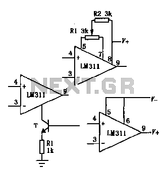
The LM111/211/311 power supply operates within a voltage range of 5V to 15V. It features bias current, offset current, and a differential input voltage range of 30V. The output is compatible with TTL, DTL, and MOS circuits, allowing it...
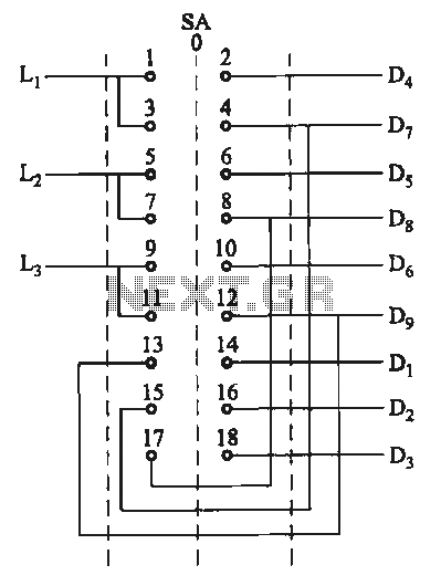
The motor switch control circuit depicted in the figure provides two speed settings for counter-steering, allowing for operation at two speeds in opposite directions. The motor switch control circuit is designed to facilitate the operation of a motor at two...
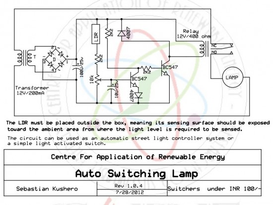
The circuit is designed to switch off a specific lamp or a group of lamps based on varying ambient light levels. Once constructed, it will turn off a lamp at dawn and turn it on at dusk. The power...
The following circuit illustrates a Water Level Detector Circuit Diagram. This circuit is based on the PIC12F683 microcontroller. Features include the ability of the PIC microcontroller to enter a sleep mode. The Water Level Detector Circuit utilizing the PIC12F683 microcontroller...
The circuit incorporates components Q, C, and ZD, which are responsible for the bias and buffer stages. Its primary objective is to ensure stable MOSFET gate operation and provide an offset voltage through a voltage buffer amplifier stage with...
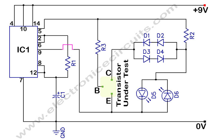
In a circuit transistor tester schematic, there is a circuit that can indicate the condition of a transistor using two LEDs. A good NPN transistor... The circuit transistor tester is designed to evaluate the functionality of both NPN and PNP...