
Motion-detection Digital Camera circuit

The described system utilizes a motion sensor to trigger a digital camera module, which captures a sequence of images upon detecting movement within a designated area. The camera, capable of operating in both high resolution (640 x 480 pixels) and low resolution (352 x 288 pixels), is equipped with a CMOS sensor and features 16 MB of internal RAM for temporary image storage.
Upon detecting movement, the system initiates a sequence where it captures 10 consecutive images at 0.5-second intervals. This rapid capture allows for a brief moment of activity to be documented effectively. After completing the burst of 10 photos, the system enters a waiting phase of 3 seconds, during which it continuously monitors for further movement. If additional movement is detected within this timeframe, the photo-capturing sequence is repeated, with a maximum limit of 80 photos.
The images captured in high resolution are approximately 115 kB each, while those taken in low resolution are around 35 kB. This difference in file size is significant for storage considerations, particularly given the camera's 16 MB of RAM, which will be cleared when the battery is depleted.
To facilitate user access to the captured images, the camera module includes a USB connection, allowing for easy transfer of photos to a personal computer for viewing and management. This feature enhances the usability of the system, making it practical for various applications, including security monitoring and event documentation. The design of this system emphasizes efficiency in capturing and storing images while providing the user with straightforward methods for accessing the data.When the sensor detects movement in a room it will take a burst of 10 photos with the digital camera. Each photo is taken at 0.5sec interval. After the 10 photos, the camera waits 3 seconds for further movement and if it is detected, the process is repeated until 80 photos are taken.
The photos can then be downloaded to your PC (via the USB connection on the board) for viewing. The camera module is 640 x 480 (High Resolution). Each photo is approximately 115k. In Low Resolution mode the photos are: 352 x 288. The photos are approx. 35kB The camera is CMOS and has 16Mb internal RAM, that is cleared when the battery is flat or 🔗 External reference
Related Circuits
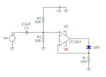
Common Light Emitting Diodes (LEDs) require a direct current (DC) forward bias of 10 to 20 mA for optimal performance. The maximum allowable DC current typically ranges from 30 to 50 mA. The emitted light color, or wavelength, from...

An RF power amplifier is an electronic amplifier used to convert a low-power radio-frequency signal into a larger signal of significant power, typically for driving the antenna of a transmitter. It is optimized for high efficiency, high output power...
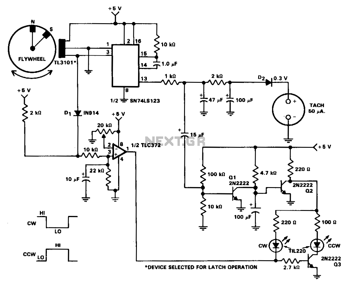
In machine and equipment design, certain applications necessitate the measurement of both shaft speed and direction of rotation. The circuit of a tachometer, which also indicates the direction of rotation, is illustrated. A flywheel is equipped with two magnets...
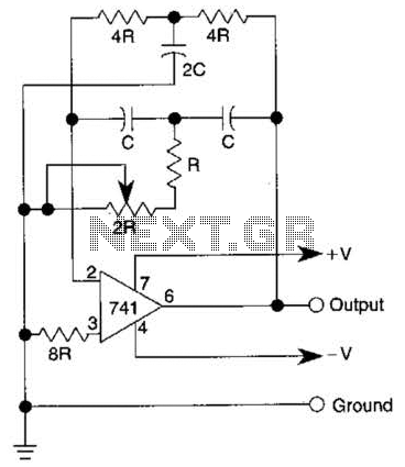
The quality of the sine wave depends on how closely the components in the twin-T network are matched in the operational amplifier's feedback loop. The twin-T network is a type of filter circuit commonly used in audio applications, signal processing,...
This circuit turns off an amplifier or any other device when a low-level audio signal fed to its input is absent for at least 15 minutes. Pressing P1 switches the device on, supplying power to any appliance connected to...
An RF field indicator is needed to verify power stages and transmitter antennas. This radio field indicator allows for the measurement of radiated energy from antennas. An RF field indicator is a crucial device in the field of telecommunications and...