
Motion Detector Alarm Circuit
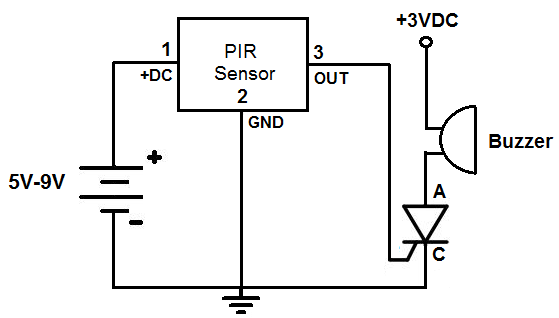
The alarm circuit integrates a Passive Infrared (PIR) motion sensor, which is pivotal for detecting movement by sensing infrared radiation emitted by warm bodies. The sensor operates effectively within a range of 20 feet (6 meters) and possesses a detection angle of 110° vertically and 70° horizontally, allowing it to cover a wide area. The PIR sensor is powered through its connection to the Arduino, with Pin 1 linked to the 5V terminal and Pin 3 to ground (GND), ensuring the sensor receives the necessary voltage for operation. The output from the sensor is transmitted via Pin 2, which connects to digital pin D3 on the Arduino.
When the PIR sensor detects motion, it outputs a high signal (approximately 3V), which the Arduino interprets as a trigger to activate the alarm buzzer connected to pin D13. The Arduino is programmed to monitor the input from the PIR sensor continuously. If the sensor output is high, indicating motion, the Arduino will turn on the buzzer, which will continue to sound until the circuit is manually powered down or reset.
This design can be adjusted based on user requirements. For instance, if a louder alarm is desired, a siren can be substituted for the buzzer, or both can be wired in parallel to ensure they activate simultaneously when motion is detected. The circuit can also be expanded with additional features, such as integrating a delay timer or a remote control for deactivation, enhancing its functionality and user convenience. Overall, this alarm circuit serves as an effective solution for motion detection and alerting, suitable for various applications in security and safety systems.This is an alarm circuit which will go off when any motion or movement is detected. Once it detects this motion, the circuit will trigger an alarm buzzer to sound which will remain on until the power is disconnected from the circuit. This alarm circuit`s most common use is to detect a person moving through an area where the motion detector can sen
se. Before this, we built a simpler motion detector circuit that turned on an LED once motion was detected. But 1 or 2 seconds after, the LED would go off. The difference between that circuit and this one which we`re now building is that an alarm must stay on once it is activated until it is manually turned off such as by shutting off all power.
If an alarm just went off once and stopped, it wouldn`t be very much of an alarm. Once motion is detected with this circuit, it will turn on the buzzer, which will buzz until the circuit is manually disconnected. This is similar to an alarm only shutting off when a homeowner enters in the password to turn it off.
A very good buzzer which can be used is a 1. 5-3V metal buzzer which can be found at allelectronics. com. This is a very low-voltage buzzer which only needs 1. 5V to 3V to operate. However, you can use any buzzer that can operate at 5V of power or less. If you only have buzzers that need more voltage, then you`ll have to power the buzzer with an external power source. Instead of connecting the anode of the buzzer to the 5V terminal of the arduino, you would connect it to an external voltage source, giving it the necessary voltage the buzzer would need.
The main electronic component we will use that allows us to pick up this detection is the PIR motion sensor. The PIR motion sensor is a sensor which detects movement through picking up infrared waves. Being that a person emits infrared radiation, the detector is able to detect this radiation and react, according to the how the circuit is designed to react.
Being that people naturally give off infrared radiation (heat energy), because of our generated body heat, the sensor can easily detect people walking and moving through a vicinity within the sensor`s range. The sensor can also pick up the movement of inanimate objects as well, such a rolling ball, because as these objects move, friction acts on them, generating heat.
This heat emits infrared radiation, which the PIR sensors may be able to detect if enough radiation is given off. The motion sensor has a sensitivity range up to 20 feet (6 meters) and a 110G‚ ° x 70G‚ ° detection range, making it a wide lens detection sensor.
This means it can measure 110G‚ ° vertically (from top to bottom) and 70G‚ ° horizontally (from left to right). The best way to check its sensitivity is when the circuit is built, try moving around through all of its angles.
See at which angles it can detect your movement and at which angles it is not able to detect your movement, meaning you`re out of its angle scope. A lot of it is trial and error and experimenting. Once you know where it can and cannot detect, you can place it in an optimal place where it can detect in areas where you want it to.
Pin 2 is the output pin of the PIR module. This is where the output of the PIR will leave from. When motion is detected by the PIR, its output will go high to 3V. When no motion is detected, its output low and it gives off practically no voltage. When high you can see then how it can power a load, such as a buzzer. This way we can know when it has detected motion or not. In our circuit, we will connect the PIR motion sensor to the power terminals of the arduino and the output pin to digital pin D3 of the arduino. Pin 1 of the PIR sensor connects to the 5V terminal of the arduino. Pin 3 connects to the ground (GND) terminal of the arduino. These pins are how the motion sensor receives the power it needs to operate. Pin 2, the output pin of the PIR sensor, connects to digital pin, D3, of the arduino. And it is through pin 3 that the arduino receives output from the motion sensor. When the motion detector does not detect any motion, the output is LOW and the arduino receives no voltage signal.
When the sensor detects motion, the output is HIGH and the arduino receives a voltage signal, which can then trigger another device to turn on, such as a buzzer we will use for this circuit. Again, once motion is detected, the PIR motion sensor will send a voltage signal to pin D3 of the arduino.
When the arduino board detects this signal, it will turn on the buzzer connected to pin D13 on the arduino. The first block of code chooses the pin for the buzzer, which is pin 13. The second line chooses the pin for the input pin, which represents the PIR sensor, pin 2. The third block of code reads the input value and assigns it to the integer named value. It reads whether the input pin is HIGH or LOW. If it is HIGH, then the motion sensor has detected motion. If it is low, the sensor has not detected any motion. If the value is HIGH, it turns the buzzer on, signaling that motion has, in fact, been detected. Once motion has been detected, the buzzer sounds and stays on. It doesn`t shut off. This simulates an actual real-life alarm system, where an alarm goes off and doesn`t shut off unless the homeowner manually shuts it off.
Several variations of this circuit can be done to fit your needs. Maybe you don`t want a buzzer to sound and you actually want sirens to go off. In that case, you would swap out the buzzer for sirens. Maybe you want sirens and a buzzer to go off. In that case, you would wire the buzzer and the siren in parallel. With sufficient current, both will go off when the alarm is triggered by motion. You can customize the circuit to fit your needs. 🔗 External reference
Related Circuits

A dual-tone model train horn/sound generator/simulator circuit can be created using two NE 555 timers connected in cascade. However, the circuit diagram presented is designed with the NE 556 integrated circuit, which essentially comprises two 555 timers in a...
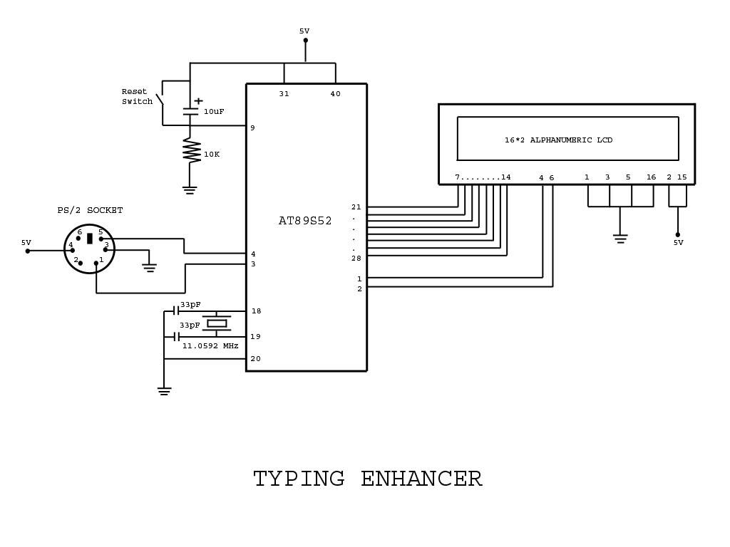
Project with Circuit and Code for a Typing Assistant using the 8051 microcontroller (AT89S52) and the PS/2 keyboard port of a computer. The project also explains the interfacing of the PS/2 port of a computer with the 8051 microcontroller. The...
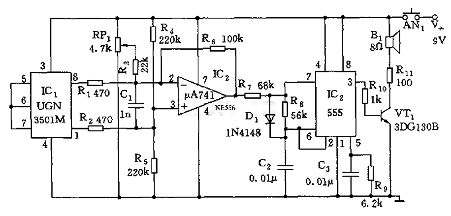
The circuit consists of a 555 timer and associated components designed for voltage-to-frequency conversion. It is utilized for determining the orientation of Earth's magnetic field using a Hall-effect sensor, specifically the UGN-3501M. This sensor incorporates a Hall element and...

User Agreement & Disclaimer Disclaimer: All files are found using legitimate search engine techniques. This site does not condone hacking into sites to create the links it lists. It is assumed that all links found on the search...
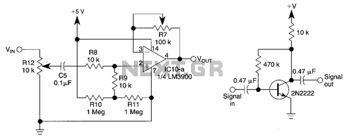
This circuit utilizes one-quarter of an LM3900 to create a simple variable-gain front end for an oscilloscope. R7 serves as the gain control. Additionally, a basic preamplifier is included for applications requiring more than 10X gain. The circuit employs the...

A simple digital circuit is presented that can be used to precisely control the AC power supply. This circuit does not include a digital-to-analog conversion component. In its application, effective control is established through a computer system that sends...