
Motion Detector Sensor Circuit
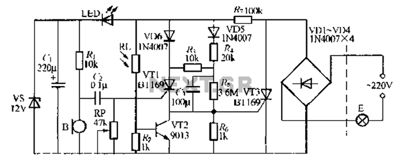
This motion detection circuit operates by emitting infrared light through the LED, which is then detected by the phototransistor. When an object moves within the detection range, it disrupts the infrared light beam, causing a change in the output signal of the phototransistor. This change is processed by the NE555 timer, which is configured in an astable mode to generate a continuous square wave output. The frequency of this output can be adjusted by varying the resistors and capacitors connected to the NE555 timer.
The LM1458 operational amplifier is utilized to amplify the output signal from the phototransistor, ensuring that even minor changes in the infrared light intensity are detected effectively. The amplified signal can be used to drive additional components, such as an alarm or a visual indicator (e.g., an LED), to alert users when motion is detected.
The PCB design for this circuit should ensure proper placement of components to minimize interference and optimize performance. It is essential to consider the power supply requirements for the NE555 timer and the LM1458 operational amplifier, as well as the appropriate biasing for the phototransistor to ensure sensitivity to motion. Overall, this infrared motion detection circuit is suitable for various applications, including security systems, automated lighting, and energy-saving devices.This circuit is a motion detection sensor, this circuit uses a light source and detector as a sensor infrared motion detector. motion detection, detection sensor, sensor, infrared, LED, phototransistor, transmitter, receiver, NE555, astable multivibrator, LM1458, PCB, circuit board,.
🔗 External reference
Related Circuits
A clock-and-data recovery (CDR) circuit is utilized to recover the clock from a transmitted data stream and re-time that data with the recovered clock. These circuits are generally positioned at the front-end of receiver chips to extract the clock...
The circuit consists of a temperature sensor, electronic switches for temperature control, and a vocal language output system. During hot summer months, the central processing unit (CPU) of PCs frequently experiences overheating. The circuit, with VT1 positioned near the...
A relatively simple circuit for controlling a stair walkway light with a delay feature. The circuit has a drawback in that the voice activation is somewhat less sensitive, making it sometimes difficult to trigger with general conversation. However, it...

Traditional control methods for fan power equipment involve manual or relay control, which often leads to issues of poor reliability and flexibility. For instance, when the motor capacity is large, the startup process can be prolonged, resulting in high...
This circuit is designed to indicate, via a flashing LED, when room noise exceeds a predetermined threshold, selectable from three fixed levels: 50 dB, 70 dB, and 85 dB. The circuit utilizes two operational amplifiers to amplify the sound...

This circuit diagram represents a lamp flasher powered by mains electricity. It is capable of flashing lamps with a maximum power of 200 Watts at user-defined rates. The NE555 integrated circuit is configured as an astable multivibrator, generating the...