
motion detector sensor circuit
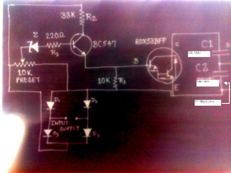
This motion detection sensor circuit is designed to detect movement by utilizing infrared technology. The transmitter section comprises an NE555 timer configured in astable mode, which generates a square wave signal at a frequency of 5 kHz. This signal drives an infrared LED that emits modulated infrared light. The modulation helps to distinguish the infrared signal from ambient light, enhancing the sensor's performance in various lighting conditions.
The receiver section consists of a phototransistor that is sensitive to the infrared light emitted by the transmitter. When the infrared light is interrupted by a moving object, the phototransistor's output changes state. In the absence of motion, the LM1458 operational amplifier maintains a low output on pin 7, indicating no detection. However, when motion is detected, the phototransistor allows current to flow, resulting in a high output (5 volts) from the LM1458.
This output can be utilized to trigger an alarm or alert system, such as a buzzer or speaker, providing an audible indication of motion detection. The circuit layout can be implemented on a printed circuit board (PCB), which simplifies construction and ensures reliable connections between components. The PCB design is available for download, allowing for easy replication of the motion detection sensor circuit. This design is suitable for various applications, including security systems, automated lighting, and occupancy detection.This circuit is a motion detection sensor, this circuit uses a light source and detector as a sensor infrared motion detector. Motion sensor using infrared LED and phototransistor. Because it uses light to the sensor sensitivity can be affected by environmental disturbances, such as wind, waste, or stray light.
In this schematic is divided into t wo schematic transmitter and receiver. Transmitter circuit is controlled by the NE555. NE555 astable multivibrator configuration installed. Infrared LED mounted on the output of a schematic and generate a frequency of 5 kHz. Here is a schematic drawing of motion detection sensor transmitter: At the receiver circuit of the LED infrared light captured by the phototransistor. At normal conditions ie when the sensor does not detect motion, LM1458 output on pin 7 will be value low (0 volts).
if the sensor detects movement, the LM1458 IC output on pin 7 will be value high (5 volts). IC LM1458 output can be connected with a speaker, buzzer or alarm. Here I also include a PCB (printed circuit board) of the motion detector sensor circuit and you can also download it. 🔗 External reference
Related Circuits
The circuit (before flameout) worked like this: device Q1 is a triac, which is a power-switching device. When triggered, it switches to a fully conducting state and stays that way until the current passing through it goes to zero....
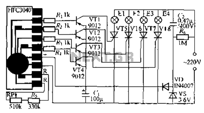
The circuit utilizes a four-way slowly dimming LED driver integrated with iU shoe production and a Qis four flashing lights string controller. The C3484 manifold is specifically designed to operate Ji lights with four lights that flash and slowly...
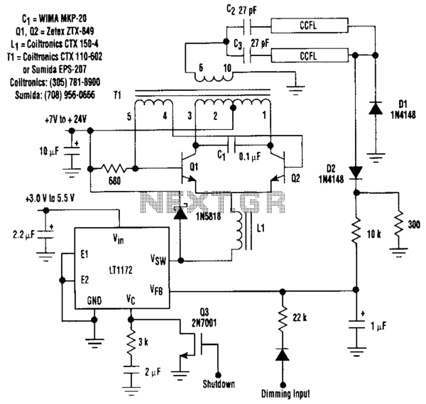
This circuit is a 92%-efficient power supply for cold-cathode fluorescent lamps (CCFLs), which are used to backlight LCDs in portable equipment. The efficiency depends heavily on the component types, particularly C1, Q1, Q2, L1, and T1, whose manufacturers are...
A simple audio amplifier with a 10 Vpp output designed for use with the AD633 ring modulation chip. The datasheet for the chip is available, and the circuit will utilize the XR2206 function generator IC for the modulation input....
The post discusses a simple delay ON circuit that enables a connected load to be powered on with a predetermined delay after the power switch is activated. This circuit is applicable for any scenario that requires an initial delay...
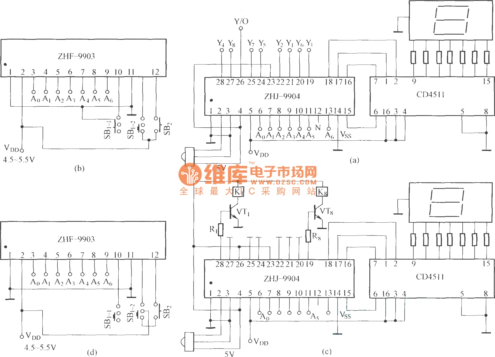
This is an eight-way signal remote control selection circuit composed of ZHJ-9904. It includes a remote control transmitter circuit, an eight-way switch control circuit, and a remote control transmitter. The eight-way signal remote control selection circuit utilizing the ZHJ-9904 is...
Warning: include(partials/cookie-banner.php): Failed to open stream: Permission denied in /var/www/html/nextgr/view-circuit.php on line 713
Warning: include(): Failed opening 'partials/cookie-banner.php' for inclusion (include_path='.:/usr/share/php') in /var/www/html/nextgr/view-circuit.php on line 713