
Neon Lamp Dimmer circuit
So what, you ask. Why did the dimmer die, and what's this got to do with neon? The problem is this: with a light bulb as a load, once the triac is triggered on, voltage is applied to the bulb, which immediately conducts current. This current keeps the triac turned on until the current cycles to zero, some milliseconds later. The neon transformer, however, is a partially inductive load, not purely resistive, like the light bulb. Applying voltage to an inductive load does not cause current to immediately flow - it takes a little time. The problem is, it takes too much time for C1, which uses up all its charge before the neon transformer gets going, and triac Q1 turns off again. This allows C1 to start charging again, during the same line voltage half-cycle! This process repeats, at breakneck speed, until the diac overheats and dies.
Herein lies the secret: What we need to do is somehow keep trigger current flowing into Q1 long enough for the neon transformer to get going, without overheating diode D1. I did this, as shown in Fig. 2.
Fortunately, when I was buying dimmers, I somehow had the sense to buy two of them. With my first dimmer lying in smoldering ruin on the bench, there was not much left to do but scrap it out for parts, the most useful being the still good triac, Q1.
Opening up the second dimmer, I mounted the salvaged triac, now known as Q2, onto its frame. (Note: at three bucks for a dimmer, it's probably the easiest way to get the triac.)
I rewired the dimmer as shown. Added resistor R2 is a 3500 ohm, 5 watt power resistor. I mounted it to the dimmer frame (as a heat sink) with a small bracket and some silicone grease. Wire the modified circuit EXACTLY as shown in Fig. 2. Reassemble the dimmer cover, using small screws in place of the original rivets or pins.
Note the colors of the new wires: they are critical, as there are now three of them. When connecting up the finished unit, make sure the white wire goes to neutral, as does one end of the neon transformer. The other end of the transformer goes to the red wire. The black wire goes to the hot AC supply. The switch MUST break the black wire!
The new circuit works like the original, with the following exceptions: (1) When D1 triggers, it turns on triac Q2. Because it has a resistive load (R2), it turns on immediately. Current through Q2, limited to a reasonable level by R2, continuously triggers triac Q1, giving the transformer enough time to start drawing power. Later, as the line voltage goes to zero, Q2 turns off, removing drive from Q1, which, because of the transformer's inductive current time lag, turns off sometime after zero crossing.
Miscellaneous notes: the triacs used in dimmers seem to be internally insulated from their mounting tabs, allowing them to be directly attached to the (grounded) dimmer frame. Units purchased from Radio Shack and elsewhere may not be insulated, and thus require insulating mounting hardware. [Update 9/96: I have found that it is not necessary to mount Q2 to the dimmer frame, as it dissipates virtually no power. I now suspend the triac by its leads. This makes the use of Radio Shack triacs viable.] In some (really cheap) dimmers, diode D1 is located inside the triac, in case you can't find the diode in your unit. In the modified circuit, this is OK for Q2 but not for Q1. If you use one of these combo units for Q2, eliminate diode D1. In my dimmer, R1 was 250 ohms, C1 was 0.1 µF, C2 (keeps line noise from false-triggering triac Q1) was 0.047 µF, L1 (value unknown, came with dimmer) helps keep switching noise from leaving the dimmer.
Application notes: (1) DO NOT use this circuit with high power factor type transformers or solid state type transformers. It won't work. (2) It sometimes helps to use a higher than normal transformer secondary voltage if you're going to operate neon down to very low brightness levels. Experiment to see what you need. (3) Working with 120 VAC is dangerous. Use all possible caution. To limit flame and damage during bench testing, temporarily connect a high-wattage light bulb in series with your AC supply wire. This limits the maximum current flow in case of a short. (4) A final note: never work on the high-voltage wiring to your tubes on a dimmer-controlled setup unless you KNOW the power is off. With a dimmer turned all the way down, your neon may not light up, but you will if you grab the wiring.
The described circuit utilizes a triac (Q1) as the primary switching device, which is controlled by a diac (D1) and a capacitor (C1) in conjunction with a variable resistor (R1). The operation begins when the AC voltage crosses zero, allowing current to flow through R1, which charges C1. The voltage across C1 increases until it reaches the breakdown voltage of D1, at which point D1 conducts, triggering Q1 and allowing current to flow to the load. The timing of this triggering is crucial for dimming the load, as it determines the amount of power delivered during each half-cycle of the AC waveform.
In the modified circuit, a second triac (Q2) is introduced to maintain the triggering of Q1 in scenarios where the load is inductive, such as a neon transformer. R2 serves to limit the current flowing through Q2, ensuring it operates within safe limits while providing adequate trigger current to Q1. This configuration allows for a more stable operation under varying load conditions, preventing premature turn-off of Q1 due to the delayed current rise associated with inductive loads.
The circuit requires careful assembly and adherence to safety protocols, especially when dealing with high voltages. Proper insulation and secure connections are essential to prevent electrical hazards. The notes provided emphasize the importance of using the correct components and configurations to ensure reliable performance and longevity of the dimmer circuit.The circuit (before flameout) worked like this: device Q1 is a triac, which is a power-switching device. When triggered, it switches to afully conducting state, and stays that way until the current passingthrough it goes to zero.
As it is connected to the alternating current, which changes direction 120 times a second, it will be turned off asoften. The trick to making it "dim" lies in how and when you turn it on. That task is left to components R1, C1, and D1. Assume the following: the alternating voltage applied to the upper black wire in fig. 1 has just (timewise) crossed through zero and is increasing. Current starts to flow through pot R1 (the thing on the other end of the plastic knob) and starts charging up capacitor C1.
As you turn the knob clockwise, you decrease the resistance of R1,causing C1 to charge faster. C1 will charge up until it reaches the breakdown voltage of diode D1 (known as a diac). In my unit, this occurs around 20 volts. Once diode D1 reaches its breakdown point, it switches into aconducting mode, discharging C1 into triac Q1, turning it on (once on, power is no longer available to R1, keeping it from recharging C1 for the duration). This whole process repeats 120 times a second. Because the time delay caused by the charging of C1, the portion ofthe AC cycle over which Q1 conducts regulates the time periodduring which power is applied to the light bulb load, and thus itsbrightness.
So what, you ask. Why did the dimmer die, and what's this got to do with neon? The problem is this: with a light bulb as a load, once the triac is triggered on, voltage is applied to the bulb, whichimmediately conducts current. This current keeps the triac turned on until the current cycles to zero, some milliseconds later. The neon transformer, however, is a partially inductive load, not purelyresistive, like the light bulb.
Applying voltage to an inductive load does not cause current to immediately flow - it takes a little time. The problem is, it takes too much time for C1, which uses up all its chargebefore the neon transformer gets going, and triac Q1 turns off again.This allows C1 to start charging again, during the same line voltagehalf-cycle!
This process repeats, at breakneck speed, until the diac overheats and dies. Herein lies the secret: What we need to do is somehow keep trigger current flowing into Q1 long enough for the neon transformerto get going, without overheating diode D1. I did this, as shown in Fig. 2. Fortunately, when I was buying dimmers, I somehow had the sense to buy two of them. With my first dimmer lying in smoldering ruin on the bench, there was not much left to do but scrap it out forparts, the most useful being the still good triac, Q1.
Opening up the second dimmer, I mounted the salvaged triac, now known as Q2, onto its frame. (Note: at three bucks for a dimmer, it's probably the easiest way to get the triac.) I rewired the dimmer as shown. Added resistor R2 is a 3500 ohm, 5 watt power resistor. I mounted it to the dimmer frame (as a heat sink) with a small bracket and some silicone grease. Wire the modified circuit EXACTLY as shown in Fig. 2. Reassemble the dimmer cover, using small screws in place of the original rivets orpins. Note the colors of the new wires: they are critical, as there are now three of them. When connecting up the finished unit, make sure the white wire goes to neutral, as does one end of the neontransformer.
The other end of the transformer goes to the red wire. The black wire goes to the hot AC supply. The switch MUST break the black wire! The new circuit works like the original, with the following exceptions: (1) When D1 triggers, it turns on triac Q2. Because it has a resistive load (R2), it turns on immediately. Current though Q2, limited to a reasonable level by R2, continuously triggers triac Q1,giving the transformer enough time to start drawing power.
Later, as the line voltage goes to zero, Q2 turns off, removing drive from Q1, which, because the transformer's inductive current time lag, turnsoff sometime after zero crossing. Miscellaneous notes: the triacs used in dimmers seem to be internally insulated from their mounting tabs, allowing them to bedirectly attached to the (grounded) dimmer frame.
Units purchased from Radio Shack and elsewhere may not be insulated, and thusrequire insulating mounting hardware. [Update 9/96: I have found that it is not necessary to mount Q2 to the dimmer frame, as it dissipates virtually no power.
I now suspend the triac by it's leads. This makes the use of Radio Shack triacs viable.] In some (really cheap) dimmers, diode D1 is located inside the triac, in case you can't find the diodein your unit. In the modified circuit, this is OK for Q2 but not for Q1. If you use one of these combo units for Q2, eliminate diode D1 . In my dimmer, R1 was 250 ohms, C1 was 0.l uf, C2 (keeps line noise from false-triggering triac Ql) was 0.047 uf, L1 (value unknown, came with dimmer) helps keep switching noise from leaving the dimmer.
Application notes: (1) DO NOT use this circuit with high power factor type transformers or solid state type transformers. Itwon't work. (2) It sometimes helps to use a higher than normal transformer secondary voltage, if you're going to operate neon downto very low brightness levels.
Experiment to see what you need. (3) Working with 120 VAC is dangerous. Use all possible caution. To limit flame and damage during bench testing, temporarily connect ahigh-wattage light bulb in series with your AC supply wire. This limits the maximum current flow in case of a short. (4) A final note: never work on the high-voltage wiring to your tubes on a dimmer-controlled setup, unless you KNOW the power is off.
With a dimmer turned all the way down, your neon may not light up, but you will ifyou grab the wiring. 🔗 External reference
Related Circuits
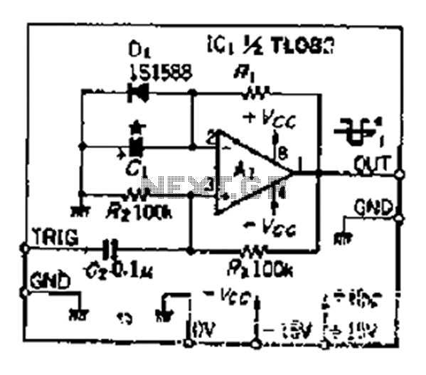
Although people believe that using a timer with an operational amplifier (op-amp) does not yield significant results, it can still be advantageous in certain scenarios. In environments with high noise levels, the application retains its benefits. When the phase...
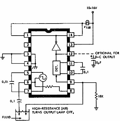
This electronic liquid detector circuit diagram utilizes the ULN2429A monolithic bipolar integrated circuit, which is designed to detect the presence or absence of various types of liquids. The detection mechanism involves comparing the resistance of a probe immersed in...
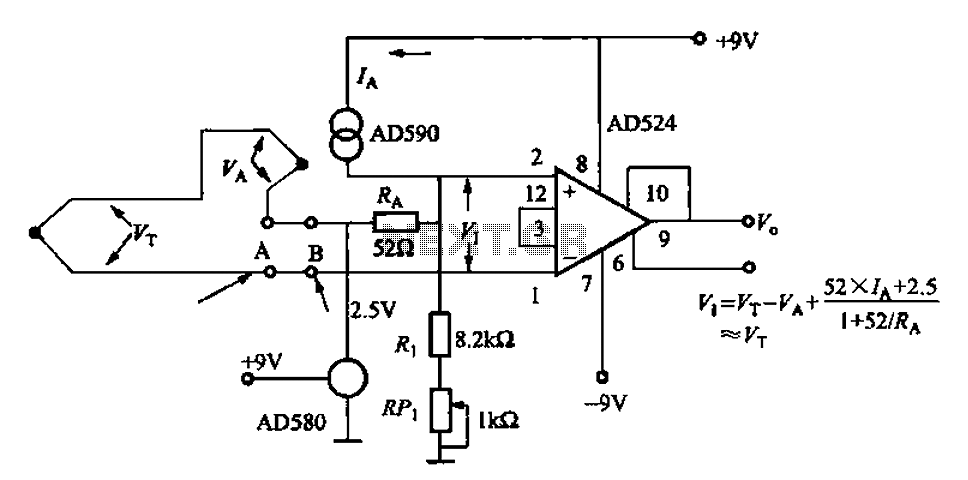
The AD524J type thermocouple cold junction temperature compensation circuit is illustrated in Figure 1-20. This circuit utilizes J-type thermocouples, with the base reference voltage sourced from the AD580, an integrated temperature sensor, and the precision instrumentation amplifier AD524. The...

This simple circuit drives six LEDs in a "Knightrider scanner mode." Power consumption primarily depends on the type of LEDs used, particularly when utilizing a 7555 (the CMOS version of the 555 timer). The circuit is designed to create a...
This circuit operates at potentially lethal 220V AC mains voltage. The circuit should be built and used only by individuals who know how to safely work with such dangerous voltages and how to construct the circuit to ensure safety....
The concept behind a light dimmer is to control the voltage supplied to a lamp or light source. Light dimmers regulate this voltage, allowing for an increase or decrease in light intensity. They first appeared in the market around...
Warning: include(partials/cookie-banner.php): Failed to open stream: Permission denied in /var/www/html/nextgr/view-circuit.php on line 713
Warning: include(): Failed opening 'partials/cookie-banner.php' for inclusion (include_path='.:/usr/share/php') in /var/www/html/nextgr/view-circuit.php on line 713