
Motion Detector with PIR Sensor
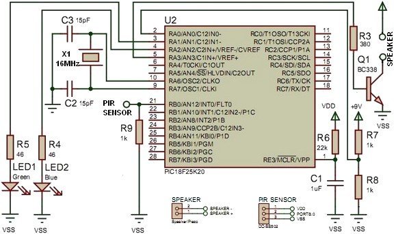
This electronic circuit is designed around the PIC18F25K20 microcontroller, which serves as the central processing unit. The microcontroller is programmed to monitor a passive infrared (PIR) sensor, which detects motion by measuring changes in infrared radiation. When the PIR sensor detects movement, it triggers an interrupt, allowing the microcontroller to respond swiftly.
The initial battery voltage check at startup is crucial for ensuring that the system operates within its specified voltage range. This feature helps prevent unexpected behavior due to low battery conditions. The microcontroller's firmware includes a routine to read the analog voltage level from the battery, ensuring that it is sufficient for operation.
The use of an RC delay filter composed of resistor R6 and capacitor C1 is essential for stabilizing the signal from the PIR sensor. This filter smooths out transient spikes or noise that may occur when the sensor detects motion. The time constant of the RC circuit, calculated using the formula τ = R × C, determines the duration of the delay. This delay is critical for allowing the microcontroller to settle into a known state before processing sensor inputs, thereby reducing the likelihood of erroneous readings that could lead to circuit malfunction.
The output from the microcontroller is directed to a speaker or piezo buzzer, which provides an audible alert when motion is detected. The design ensures that the sound output is both timely and reliable, enhancing the effectiveness of the motion detection system. Overall, this project integrates key electronic components and principles to create a robust motion detection and alert system.this project use PIC18F25K20 microcontroller to detect if the sensor change state and it will emit a sound from the speaker or piezo, the MCU also detect the voltage of the battery in the startup, the algorithm it s very simple use an interrupt on change to detect the change on the PIR sensor. Power On - when circuit start, a delay come to MCU ge nerate a unknowed state, to avoid circuit malfunction, R6 and C1 make a RC delay filter, calculate delay with: 🔗 External reference
Related Circuits
If a sensor is resistive, an alternating current (AC) is equivalent to pulsed direct current (DC), and the sensor will degrade based on the root mean square (RMS) value of the AC signal. Applying 1V AC RMS is effectively...
The following circuit illustrates a Water Level Detector Circuit Diagram. This circuit is based on the PIC12F683 microcontroller. Features include the ability of the PIC microcontroller to enter a sleep mode. The Water Level Detector Circuit utilizing the PIC12F683 microcontroller...
A car battery deteriorates with use, typically lasting no more than four years. Initially, its voltage may drop to just 2V when cranking the engine. As the battery ages, its internal impedance increases, leading to a higher voltage drop...
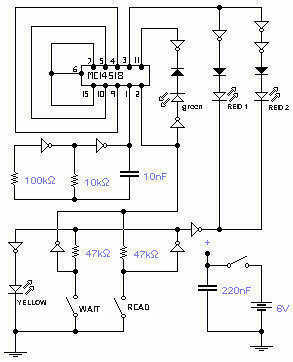
This circuit is the electronic emulation of the I Ching, a form of divination originating in China. In the classical form, the response is obtained by the manipulation of 50 sticks or, more practically, by tossing 3 coins. The...
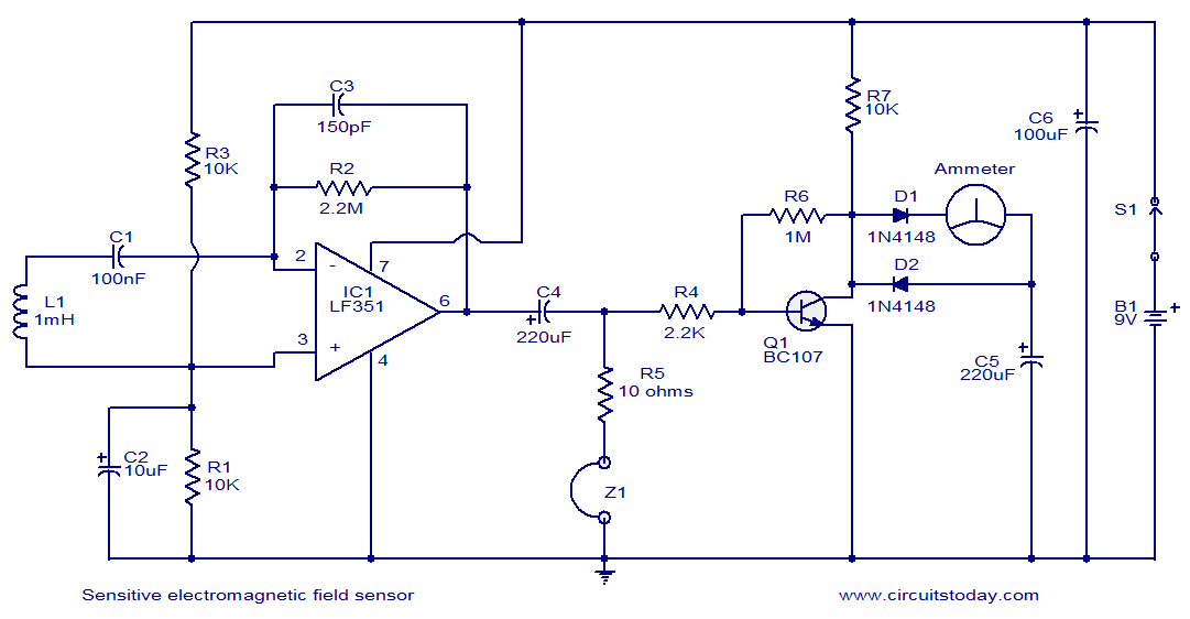
This circuit diagram represents a highly sensitive electromagnetic field sensor capable of detecting electromagnetic fields in the frequency range of 40Hz to 140Hz. The low-noise operational amplifier LF351, along with its associated components, comprises the pick-up section. A 1µH...
A live-line detector is a circuit designed to identify the presence of a live mains conductor through capacitive coupling between the live conductor and the detection circuit. The live-line detector operates on the principle of capacitive coupling, which allows it...