
Controller Area Network TDS2020F

The Controller Area Network (CAN) is a robust communication protocol designed for real-time applications in automotive and industrial environments. The system is built around a bus topology, where all nodes share a common communication line, facilitating efficient data exchange. The dual twisted pair cabling not only provides a pathway for data transmission but also ensures that power is delivered to remote nodes, enabling a simplified wiring scheme.
Each node's configuration is critical for network integrity. The DIL switches allow for easy node identification, which is essential for debugging and network management. The use of a TDS2020CAN module paired with either a TDS2020F or TDS9092 computer enables versatile applications, including data acquisition and control systems.
The CAN protocol’s message-oriented structure, rather than character-based, enhances its efficiency, allowing for higher data throughput and reduced latency. The maximum message length of eight bytes is sufficient for many control applications, while the dynamic identifier allocation offers flexibility in network configuration, making it easy to adapt to changing requirements.
The daisy-chaining of nodes simplifies the physical layout of the network, reducing cable clutter and installation complexity. The inclusion of terminating resistors is crucial for minimizing signal reflections, ensuring reliable communication over long distances, up to 1000 meters.
Opto-isolation further enhances system reliability by protecting sensitive electronics from voltage spikes and ground loops. This feature is particularly beneficial in industrial environments where electrical noise can interfere with communication. The ability to supply power through the CAN bus reduces the number of power supplies needed, streamlining the overall system design.
In summary, the Controller Area Network offers a robust, flexible, and efficient communication solution for various applications, particularly in environments where reliability and real-time performance are paramount. The systematic approach to node configuration, message transmission, and power distribution ensures that the network can adapt to a wide range of operational needs while maintaining high performance and reliability.The Controller Area Network data rate can be from 10kbit/s to 1Mbit/s giving recommended distances of 40 to 1000metres over two twisted pairs, one for the data, the other to carry power and ground. Up to 110nodes may be connected. 2. Set the DIL switch on each board to the required node number 0to127. The actual value is unimportant, providing the y are different —we suggest 2and3. 3. Connect together two nodes, each consisting of a TDS2020CAN with either a TDS2020F or TDS9092 computer. Use a cable with two twisted pairs, connecting pins 2&7, and 3&9, having a female connector at one end and a male at the other.
Leave the other two CAN connectors open. 7. Type CANTEST and return on each computer in turn. An incrementing number is transmitted which all connected and initialised nodes will receive and display. Verify that you see the message when you change the PC plug to the other node. Stop the test with any key (ctrl+C on TDS9092). 8. Type ROLLCALL and return on each computer in turn. A memory transfer is made to all of the 128 possible nodes and responding initialised node numbers are displayed.
In this case, just the identity of the other node should show. Controller Area Network is a bus operating at RS485 levels, 0V and +5V in push-pull to give common mode immunity. Instead of being character based, it sends messages of up to eight bytes. Each of these frames has an identifier and any node with a matching identifier will receive the message.
Each node can be either a TDS2020F+TDS2020CAN or TDS9092+TDS2020CAN combination. The number of nodes which the network can support depends on cable lengths and bit rate, but the CAN bus driver chips are specified for at least 110 nodes. The nodes are daisy-chained, the male and female CAN connectors being internally connected. Terminating resistors on the board are connected to the bus on the two end nodes by making a link, the maximum recommended network length between the terminations is 1000m.
The network needs a minimum of a twisted pair, a ground reference being provided locally at each end. However, typically a twin twisted pair cable will be used, the second carrying power. q Use of the built-in opto-isolation, power being supplied to the whole CAN side of the system through the other two wires from a separate +7to13V supply.
q Power supplied from one CAN node to all the remote computers by making links between the CAN and computer sides of the circuitry, giving only one power supply entry point to the network. A single supply of +6Vto16V will power TDS2020F and TDS9092 computers on the network. Note that if you want compliance with the Computers in Automation (CiA) specification this should be limited to +7to13V over the network.
The current consumption of the TDS2020CAN board is typically: The TDS2020CAN plugs underneath a TDS2020F or TDS9092 computer, adding 13mm to the overall height. The board size is 100x80mm. All pins from the top computer board are reproduced below the CAN board. The hardware of the TDS2020CAN conforms to the CiA Standard 102 version2. 0, which in turn is based on ISO11898. Each CAN node has a 9-pin D-plug and a D-socket connected together on the board. They are also connected, via CAN bus driver/receiver chips and high speed opto-isolators, to the CAN controller chip.
CAN nodes are daisy-chained together and 120-ohm terminating resistors join the two wires via link11 on the two end nodes. CAN bus connections are: On TDS2020CAN, every node has up to 15channels, each with its own identifier.
The identifiers are dynamic, not fixed, so software can update a system configuration. For instance, channel one may be allocated to be the only channel in each node for transmitting information and it can have a unique code. The other 14channels may be receivers and at any time be looking out for messages with matching identifiers from up to 14 other nodes.
There are many ways of using these facilities. 🔗 External reference
Related Circuits

This article continues from the previous one regarding the single character LCD display using an AVR microcontroller. The prior article demonstrated how to display a single letter on an LCD. This article advances the learning process by explaining how...
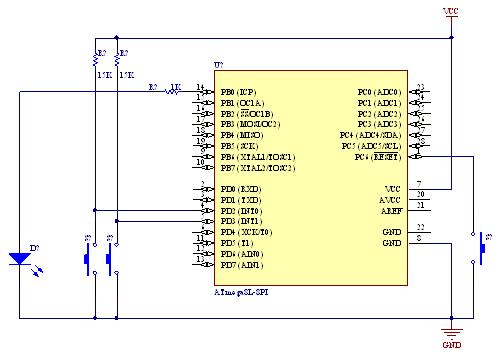
A demonstration of external interrupts in the AVR (Atmega8) microcontroller, including a circuit diagram and C code for the interrupt service routine (ISR). The Atmega8 microcontroller is a versatile device widely used in embedded systems, particularly for applications requiring external...
Faulty readings from the DS18B20 temperature sensors used in tank thermometers were likely caused by the waterproofing method involving heat shrink and silicone. This situation provided an opportunity to enhance the code for better tolerance against erroneous readings. The...
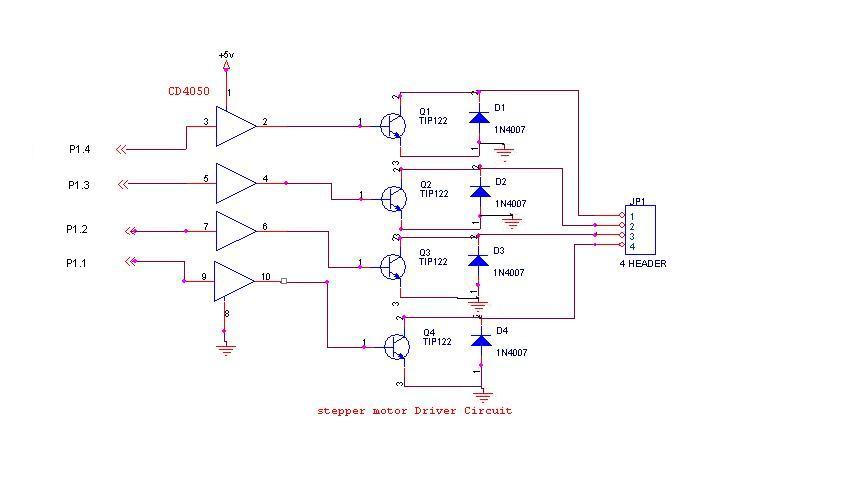
A 6V, 2A stepper motor is utilized in this circuit. The CD4050 hex buffer is employed to connect to the microcontroller. The output of the CD4050 is linked to the base of a TIP122 transistor. The emitter and collector...
Foggers used to generate fog and smoke effects operate by heating a special fogger fluid. They consist of a heating element that is maintained at the correct temperature using a thermostat. When the operator wants to generate smoke, they...
This DC drill speed controller circuit allows for the adjustment of the rotational speed of a drilling machine. A mini-drill machine is always... This circuit utilizes a pulse-width modulation (PWM) technique to control the speed of a DC motor, which...