
Suzuki GSX1300 Hayabusa Charging System Circuit (99 00)
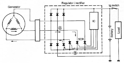
The Suzuki GSX1300 Hayabusa charging system is designed to efficiently manage the electrical power generated by the engine. The generator, typically an alternator, produces AC voltage as the engine runs. This AC voltage is then routed to the regulator/rectifier unit, which converts it to the appropriate DC voltage required for charging the battery. The regulator plays a crucial role in maintaining the battery's charge by ensuring that the voltage does not exceed the safe operating limits, thus protecting the battery from overcharging.
During low engine RPM conditions, the regulator is inactive, allowing the battery to be charged directly by the generator's output. This direct charging ensures that the battery receives power even when the engine is not running at optimal speeds, which is particularly important for starting the vehicle and powering electrical accessories.
As the engine speed increases, the output voltage from the generator rises. When this output voltage surpasses the predetermined threshold, the regulator activates, sending a control signal to the SCR. The SCR is a type of semiconductor device that acts as a switch, allowing current to flow in one direction when triggered. Once activated, the SCR allows the excess current generated by the alternator to bypass the battery, preventing overcharging and ensuring that the system remains stable.
The ability of the charging system to dynamically adjust to changes in engine speed and electrical load is essential for the reliable operation of the Suzuki GSX1300 Hayabusa. This sophisticated interplay between the generator, regulator, and SCR ensures that the vehicle's battery remains adequately charged while protecting it from potential damage caused by overvoltage conditions.The circuit of Suzuki GSX1300 Hayabusa Charging System composed of generator, regulator/rectifier unit and battery. The AC current generated from the generator is rectified by the rectifier and is turned into DC current, then it charges the battery.
While the engine rpm is low and the generated voltage of generator is lower then the adjusted volta ge of regulator, the regulator does not function. However, the generated current charges the battery directly at this time. When the engine rpm becomes higher, the generated voltage of the generator also becomes higher and the voltage between the battery terminals becomes high accordingly. When it reaches the adjusted voltage of the integrated circuit and it is turned ON , a signal will be sent to the SCR (thyristor) gate probe and the SCR will be turned ON .
Then the SCR becomes conductive in the direction from point A to point B. At this time the current generated from the generator gets through the SCR without charging the battery and returns to generator again. 🔗 External reference
Related Circuits
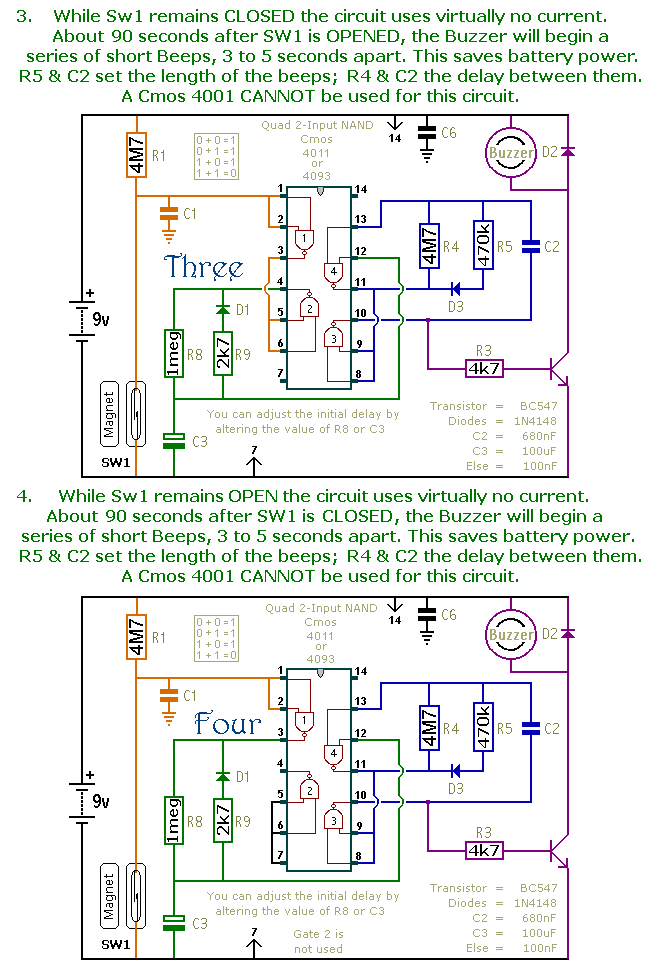
This document presents a collection of compact, self-contained alarm circuits. These circuits are designed to operate with a very low standby current, making them ideal for battery-powered applications. They can be triggered by both normally-open and normally-closed switches, while...
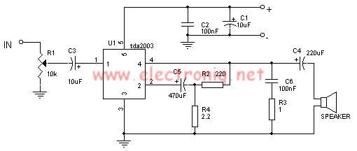
The TDA2003 audio amplifier integrated circuit can be used to design a straightforward 10-watt power audio amplifier for a 2-ohm load or 4 watts for a 4-ohm load. The TDA2003 offers high output current capacity (up to 3.5A) and...

This circuit is designed for lamp dimming and similar applications. It requires only one RC phase lag network. To prevent the hysteresis (or "snap-on") effect, the capacitor is reset to approximately 0 volts at the end of every positive...
The circuit illustrated in the figure depicts an automatic bathroom light switch system. When the door is opened, the light is activated, illuminating the space. Conversely, when the door is opened again, the light turns off. The circuit comprises...
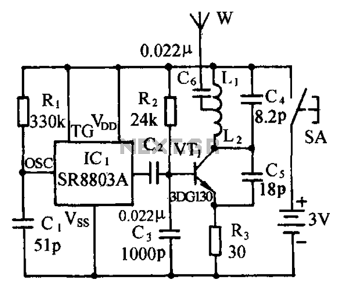
The circuit consists of a language and sound FM transmitter. It is mounted on a 25mm x 35mm PCB, designed to be placed on a table. When activated by pressing the micro switch SA, the circuit transmits an FM...
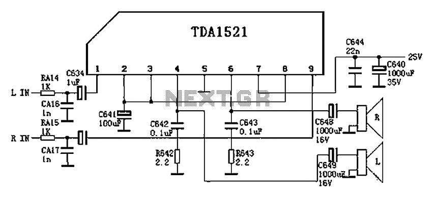
Color is often used in audio circuits like the TDA1521, which is derived from the Changhong C2191 model featuring an OTL two-channel connection. The pin functions and reference voltages for the TDA1521 are as follows: Pin 1: 11V -...