
CNC Controller Motion Schematics

The power supply circuit operates under standard conditions, beginning with the 110VAC input at connector N17. The integration of components such as the power switch SW1, fuse F1, and transformer T1 is crucial for ensuring safe operation and voltage transformation. The transformer’s secondary coil outputs 24VAC, which is then rectified to DC by the full-wave bridge rectifier BR1, providing a stable DC voltage to the controller board. The large capacitor C31 smooths out fluctuations in the rectified voltage, ensuring that the microcontroller and other components receive a consistent power supply.
Voltage regulation is managed through three separate voltage regulators (VR1, VR2, VR3), which not only provide the necessary 5V for the digital circuitry but also help dissipate excess heat generated by the load. This design choice enhances reliability and longevity of the voltage regulation process. The presence of test points for each regulator facilitates maintenance and troubleshooting.
The microcontroller U11 plays a pivotal role in interfacing with external communication protocols such as USB and RS-232, adapting the signals appropriately for seamless interaction with peripheral devices. The MAX232 chip is essential for converting RS-232 levels to compatible logic levels, ensuring effective communication.
The use of RS-422 for off-board signaling is a notable feature, as it provides robustness against electromagnetic interference, which is critical in environments with potential noise sources. The design incorporates mini-DIN connectors N6 and N7 for control and sensing signals, optimizing space and functionality on the PCB.
In summary, this power supply and control circuit is designed with careful consideration of voltage regulation, signal integrity, and noise immunity, making it suitable for reliable operation in various applications. The integration of visual indicators, such as LEDs for power status and fault conditions, further enhances user interaction and safety.The power supply is pretty mundane. The 110VAC comes in on connector N17 and is hooked in series with a power switch SW1, a fuse F1, and the primary coil of transformer T1. The secondary coil of T1 produces 24VAC at 12 Amps and is routed through the full wave bridge rectifier BR1 and onto the controller board at connector at pins 1 and 5 of N12.
A large off-board filter capacitor of 10, 000 µF (C31) is connected to the controller board at pins 2 and 5 of N12. In addition, a 24VDC cooling fan is connected at pins 3 and 6 of N12. Resistor R12 and red LED D33 will bleed off the charge of C31 when power is turned off. As long as D33 is lit, there is charge on the capacitor and extra care should be taken. The 24V primary coil is rated in RMS (Root Mean Squared), so the actual peak voltage is 24V/. 707 or approximately 35 volts. The unregulated voltage is used by the stepper and selenoid drivers as VDC. The unregulated voltage is stepped down through VR1, VR2 and VR3 to produce the 5 volts needed by the digital circuitry.
The reason for using 3 voltage regulators is because 1) the stepper motors and selenoid chopper circuits will be causing a fair amount of roughness on the unregulated voltage and 2) the amount of heat generated will be spread across 3 voltage regulators rather than just 1. While the schematic does not show it, there are test points for each of the voltage regulators on the PCB.
Lastly, power on is indicated by the green LED D34 which is current limited by R36. LED D34 is mounted off board on the chasis. The I/O microcontroller U11 is only needed if the user intends to use either the RS-232 connector N9 or the USB (Universal Serial Bus) connector N10. The PIC16C745 is needed to support both USB and RS-232, whereas a simpler PIC16F876A is can be used if only RS-232 support is needed.
The microcontroller firmware emulates the 25-pin DB25 parallel port connector N11. The microcontroller can detect the usage of the parallel port when pin 1 of N11 is pulled low; otherwise, the microcontroller detects that there is no parallel port in use by having pin 1 pulled high by R18 and assumes that some form of serial communication is going to be used. All of the RESET lines for all of the microcontrollers are tied together and pulled high by R19. The U17 MAX232 RS-232 level converter chip is used to convert between RS-232 levels and microcontroller logic levels.
Connector N10 is used for USB communication. Resistor R16 and capacitor C21 are used to indicate to the USB host that this is a slow speed line. Lastly, N14 is used to connect to an off board red fault LED D35 through current limiting resistor R9. Differential RS-422 is used for off board signalling because of the excellent high noise rejection capabilities.
Long wires tend to behave like antennas and pick up the noise from flouresent light bulbs and local HAM radio operators. RS-422 is able to avoid most of those problems. All control and sense operations are bundled into two 8-pin mini-DIN connectors N6 and N7. There was no extra board edge space fore additional conntectors. All logical level signals are converted to RS-422 voltage via the quad differential driver U13. The motor and drawbar signals are routed to N6 and the pump and "other" signal is routed to N7. In addition, two RS-422 signals are converted to regular logic levels by U10. The probe signal comes from N7 and the spindle tachometer signal from N6. Resistors R13 and R14 are line termination resistors. Lastly, any limit switches are connected together in series from N7 pin 2 to N6 pin 2. The switches are normally closed and only open when some sort limit condition is encountered. In addition, the normally closed emergency stop switch is connected across N16. If there is any open circuit in the limit switch and emergency stop chain, the EN enable line is pulled low via R17.
Otherwise, the +5 volts on pin 2 of N7 asserts the EN enable line. The X 🔗 External reference
Related Circuits
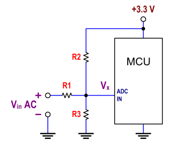
The ATtiny24 microcontroller's ADC is utilized to record an AC signal, which operates within a voltage range of 0 to 3.3V. A precision rectifier is employed to eliminate the negative portion of the signal. The circuit incorporates an LMC6484...
This design is intended as a dimmer for a 12V reading lamp, but it can also function as a motor speed controller for devices like drills. The circuit modulates the voltage supplied to the load, allowing for variable pulse...
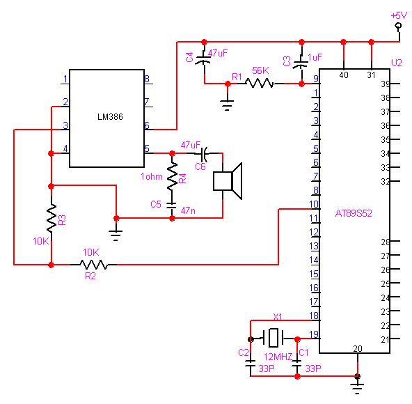
The 8051 microcontroller can play music tones. Here is a sample circuit and code that will play the music for "wishes you to be..." The 8051 microcontroller is a versatile and widely used microcontroller in embedded systems, capable of performing...
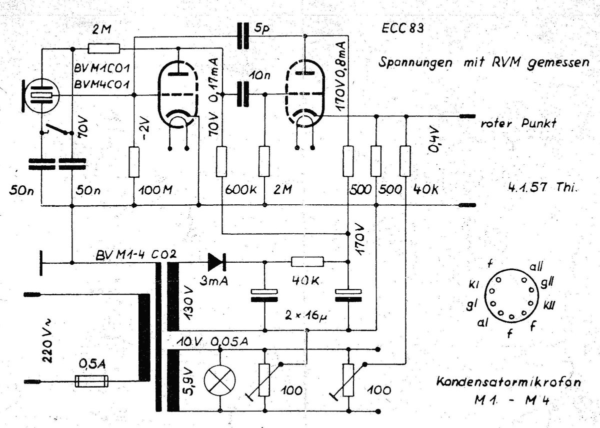
The power supply is integrated into the base of the microphone, which may cause hum issues, even with the onboard potentiometer designed to nullify this effect. Consequently, the microphone features two cables: one for power and another for audio...
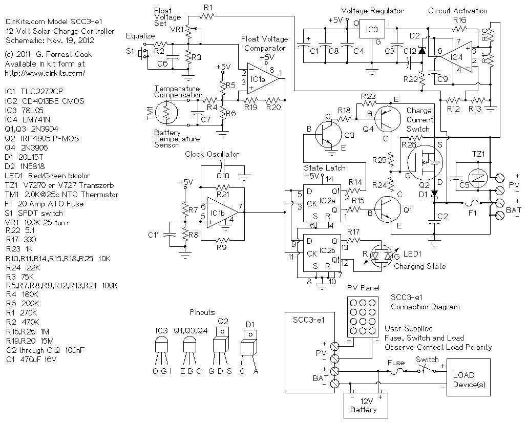
The design goals of this circuit were efficiency, simplicity, reliability and the use of field replaceable parts. A medium power solar system can be built with the SCC3, a 12V (nominal) solar panel that is rated from 100 milliamps...
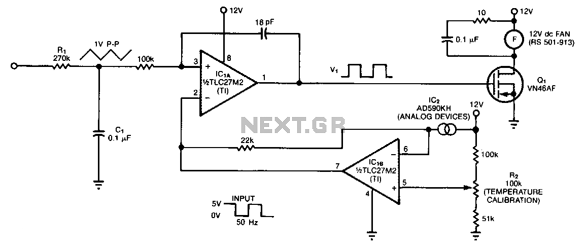
The controller circuit is designed to reduce a fan's noise, power consumption, and wear, especially when operating in low, fluctuating ambient temperatures. A temperature sensor is mounted in the fan's airstream, allowing the circuit to adjust the fan speed...