
Motor control diy
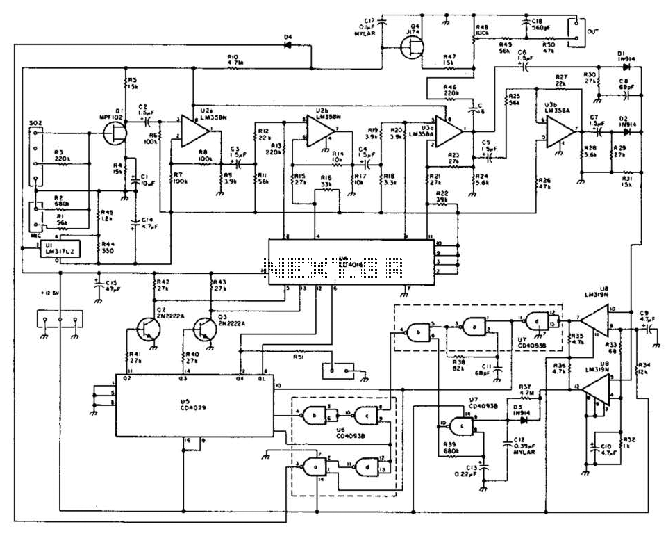
The motor in question operates at a power rating of 6 watts, which indicates that it draws a current of 0.5 amps when supplied with a voltage of 12 volts. To ensure reliable operation, a 12V DC power supply capable of delivering at least 1 amp is recommended. This allows for a margin of safety and accounts for any potential inrush current that may occur when the motor starts.
The power supply can be of various types, including a plug-in adapter, which is commonly used for such applications. When selecting a power supply, it is essential to ensure that it provides a stable output voltage of 12V and can handle the required current load.
In terms of circuit design, the motor should be connected in parallel with the power supply. It is advisable to incorporate a fuse rated slightly above 0.5 amps to protect against overcurrent situations. Additionally, a diode can be placed in parallel with the motor terminals to prevent back EMF (electromotive force) from damaging the power supply when the motor is turned off.
The overall schematic would include the following components:
1. A 12V DC power supply rated for at least 1A.
2. The motor rated at 6W, with appropriate connections to the power supply.
3. A fuse rated for 1A to protect the circuit.
4. A flyback diode across the motor to manage inductive kickback.
This configuration ensures that the motor operates efficiently while minimizing the risk of damage to the circuit components.That motor is rated for 6W which is 0.5 amps at 12V. I would use a 12V DC power supply rated at 1A or more. Any type will be OK. A plug-in adapter.. 🔗 External reference
Related Circuits
The F84 MRTC was my second design of a miniature real-time controller. This version uses PIC16F84 running with a low power X-tal 32,768Hz. The scheduler for 6-channel output was saved in EEPROM. No terminal for serial downloading of the...

This circuit enables a 4-to-20 mA current loop to control an isolated SCR drive. IC1A and IC1B function as one-shot timers. Q2 detects zero crossings of the 120 Vac line, which triggers one-shot IC1B. IC1A causes Q1 to discharge...
This method of automatic level control (ALC) utilizes digitally switched audio attenuators within the signal path. The output level of the system is monitored, compared to a reference level, and audio pads are introduced through analog switches. This technique...
This circuit diagram can be utilized to adjust the speed of a low-power induction motor, commonly found in fan applications. The circuit for controlling the speed of a low-power induction motor typically employs a variable frequency drive (VFD) or a...
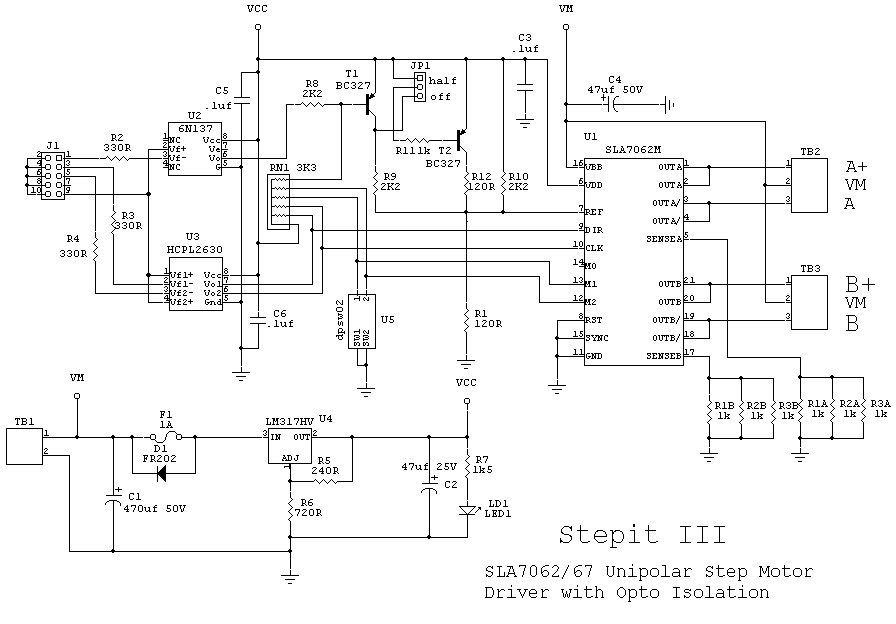
The SLA7062/67 chip is a unipolar driver capable of delivering up to 3 amps. This chip is somewhat difficult to locate and is priced at approximately $10 each. Availability was confirmed through a Google search, which yielded three units...
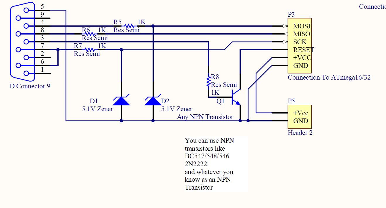
ISP programmer with circuit diagram for AVR Atmega32 microcontroller. This ISP burner circuit is an adaptation of the Pony programmer and uses PonyProg software. The ISP (In-System Programming) programmer designed for the AVR Atmega32 microcontroller facilitates the programming of the...