
ISP Programmer/Burner with circuit diagram for AVR Atmega Micro Controller
The ISP (In-System Programming) programmer designed for the AVR Atmega32 microcontroller facilitates the programming of the microcontroller directly on the target circuit. This approach allows for the microcontroller to be programmed without the need for removal from its operational environment, which is essential for applications where space and accessibility are limited.
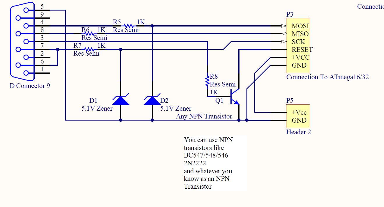
The circuit diagram for the ISP programmer typically includes a microcontroller interface, a connection to a PC, and the necessary components to support communication protocols. Key components of the circuit include resistors, capacitors, and a crystal oscillator, which are essential for stable operation and timing. The Pony programmer adaptation utilizes a serial interface for communication with the PC, allowing the user to upload firmware to the Atmega32.
Connections to the Atmega32 microcontroller are made through specific pins designated for programming. These include the MOSI (Master Out Slave In), MISO (Master In Slave Out), SCK (Serial Clock), RESET, and VCC/GND pins. The circuit must ensure proper voltage levels and signal integrity to avoid programming errors.
The software used, PonyProg, is compatible with various operating systems and provides a user-friendly interface for firmware uploading. It supports various programming modes and offers diagnostic features to ensure successful programming.
In summary, the ISP programmer circuit for the Atmega32 microcontroller is a vital tool for developers, enabling efficient firmware updates and programming directly in the application environment. The adaptation of the Pony programmer enhances its functionality and ease of use, making it an effective solution for embedded systems development.ISP programmer with circuit diagram for AVR Atmega32 micro controller.This ISP burner circuit is an adaptation of Pony programmer and uses ponyprog software.. 🔗 External reference
Related Circuits

The darkroom circuit is designed for one-time exposure and emits an audible signal when the developing time is reached. This circuit can be utilized for photofinishing large timers and other applications. It comprises components such as FET VTi, resistors,...
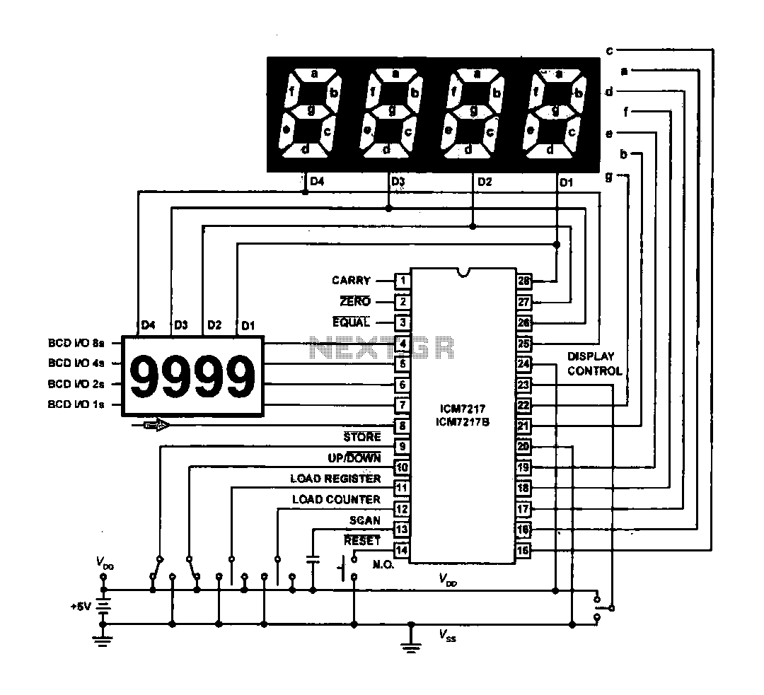
The circuit drives the light-emitting diode in a digital display configuration. The count signal is fed into the ICM7217 chip, which processes the count and subsequently drives the digital display board. The connection between the thumbwheel switches is illustrated...

877 ~ 924MHz RF2152 power amplifier circuit diagram. The RF2152 is a high-performance power amplifier designed for applications in the 877 to 924 MHz frequency range. This amplifier is typically used in various RF communication systems, including wireless networks and...
This is a 220V LED flasher circuit designed as a reliable alternative to thermally activated switches used for flashing Christmas tree lamps. It is a cost-effective and easy-to-assemble circuit. The components include R1 (100K), R2 (1K), R5 (1K), R3...

This circuit features an appealing Christmas lights setup. Upon activation, the lights (HL) gradually increase in brightness. Once they reach maximum brightness, they automatically dim, and upon reaching the lowest brightness, they gradually brighten again, creating a smooth transition...
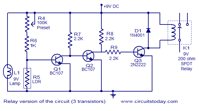
This document describes a simple fire alarm circuit utilizing a Light Dependent Resistor (LDR) and lamp combination for fire detection. The alarm activates by detecting smoke generated during a fire. When smoke is present, the circuit triggers an audible...