
Current-Loop Scr Control
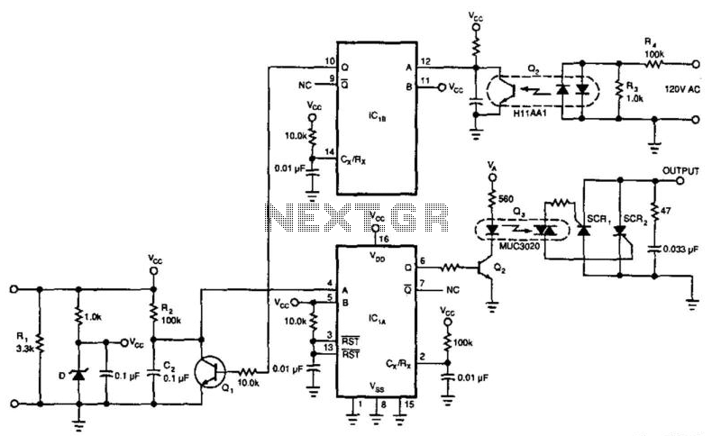
This circuit is designed to facilitate the control of devices such as motors and lighting systems through a 4-to-20 mA current loop, which is a standard in industrial automation for transmitting analog signals. The operation begins with the detection of zero crossings from the 120 Vac line by transistor Q2. This detection is crucial for synchronizing the control signals with the AC line frequency, ensuring that the SCRs are triggered at the correct phase of the AC cycle.
IC1A and IC1B are configured as monostable multivibrators, commonly referred to as one-shots. When Q2 detects a zero crossing, it sends a pulse to IC1B, which generates a timed output pulse. This output pulse is used to control the state of the SCRs, effectively allowing for the modulation of power delivered to the load.
Simultaneously, IC1A is responsible for managing the timing of capacitor C2. When triggered, IC1A causes Q1 to discharge C2, which subsequently begins to recharge through R2. The timing characteristics of this process determine the frequency and duty cycle of the output signal to the SCRs, thereby directly influencing the power delivered to the load.
The optoisolator serves to provide electrical isolation between the low-voltage control circuit and the high-voltage SCR drive circuit, enhancing safety and preventing noise from affecting the control signals. SCR1 and SCR2 are the primary switching devices that control the load, and their triggering is directly influenced by the input current from the 4-to-20 mA loop. This allows for precise control over the operation of the connected devices, making it suitable for applications where variable control is necessary, such as in dimming lights or adjusting motor speeds in response to varying input signals.
Overall, this circuit offers a robust solution for controlling high-power devices through a low-power control signal, ensuring reliability and safety in industrial applications. This circuit allows a 4-to 20-mA current loop to control an isolated SCR drive. IC1A and are one-shots. Q2 detect s zero crossings of the 120 Vac line, which triggers one-shot IC1B. IC1A causes Ql to discharge C2. When C2 recharges through R2, it triggers IC1A, and the optoisolator and SCR1/SCR2. Triggering of SCR1 and SCR2 is a function of input current, which can control motor speed, light intensity, etc. 🔗 External reference
Related Circuits
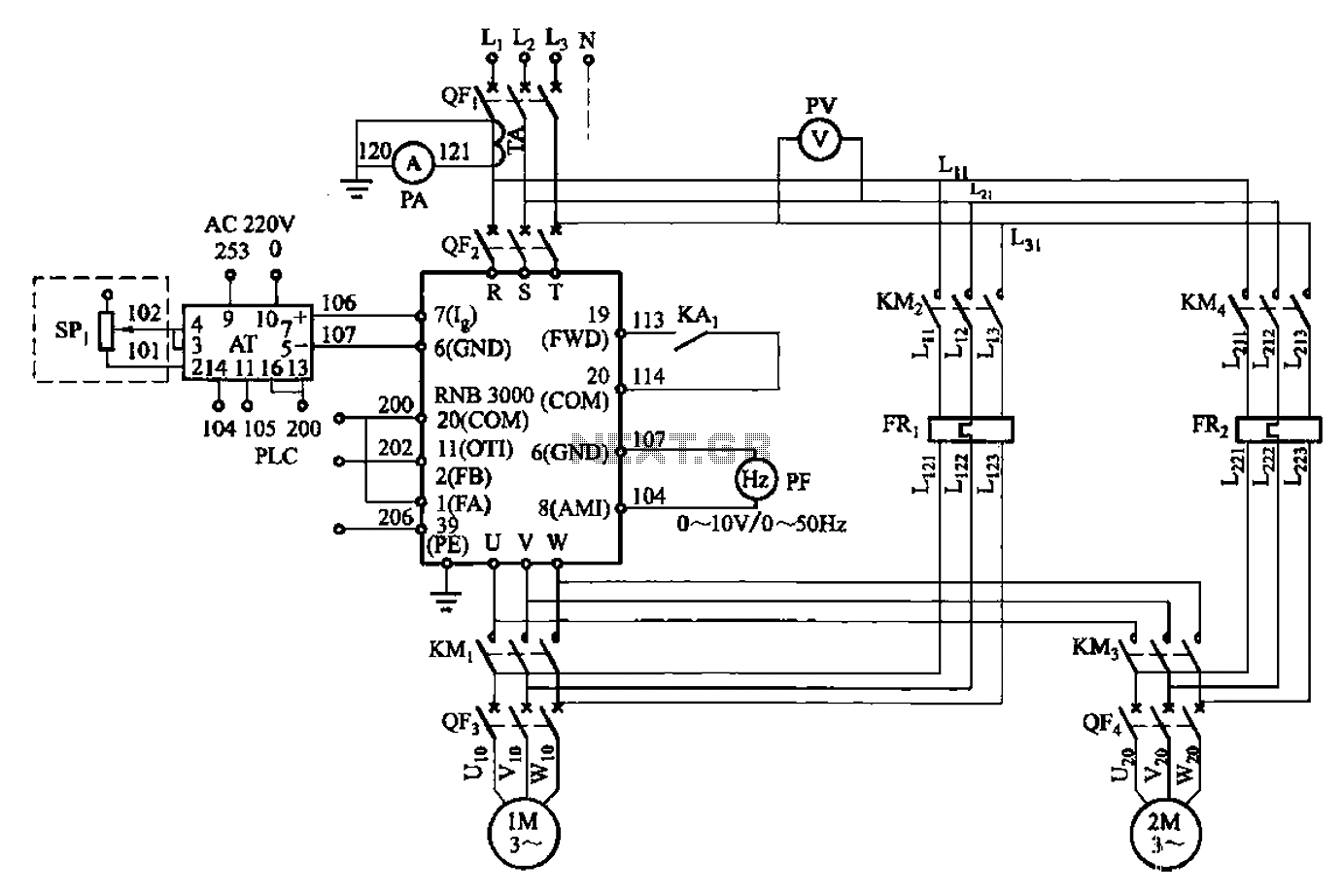
A control circuit for two motors, specifically for frequency control in a constant pressure water supply system, is illustrated in Figure 5-23. The circuit includes fault output terminals labeled 1 and 2, analog feedback current input terminals labeled 6...
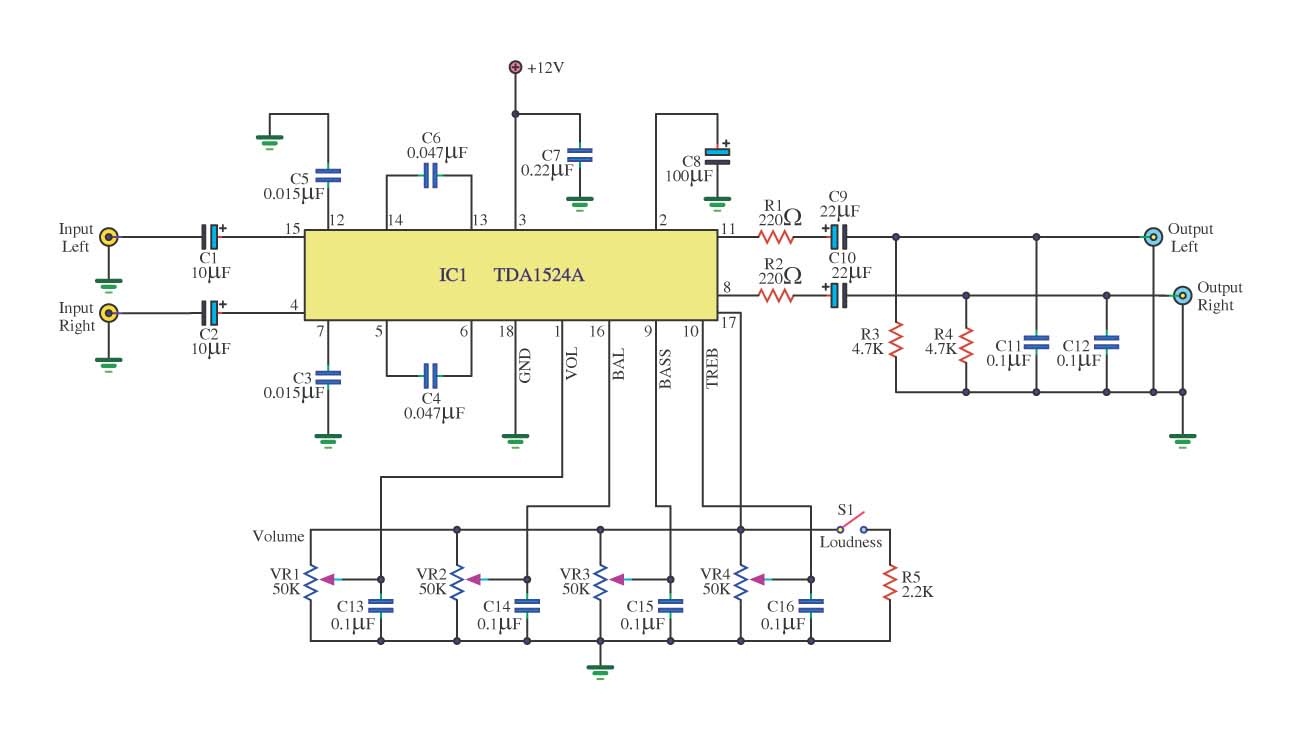
This is a simple tone control circuit using the TDA1524A, which is a key component in this IC chip diagram from Philips. The circuit allows for tone control adjustments such as bass, treble, and balance, enabling users to fine-tune...
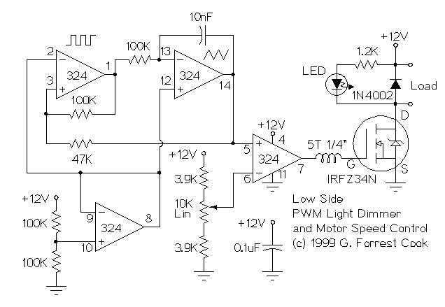
These two schematics are variations on another PWM circuit that I designed. The diagrams are for 12V operation only and there are high side (common ground) and low side (common +12V) versions. The low side version of the circuit...
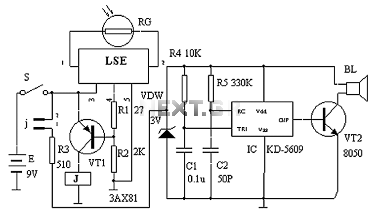
The circuit principle is illustrated in the accompanying figure. When the night light shines on the photosensitive resistor RG, it exhibits a high resistance (significantly greater than 50K). As a result, the output of the LSE pin is low,...
Foggers used to generate fog and smoke effects operate by heating a special fogger fluid. They consist of a heating element that is maintained at the correct temperature using a thermostat. When the operator wants to generate smoke, they...
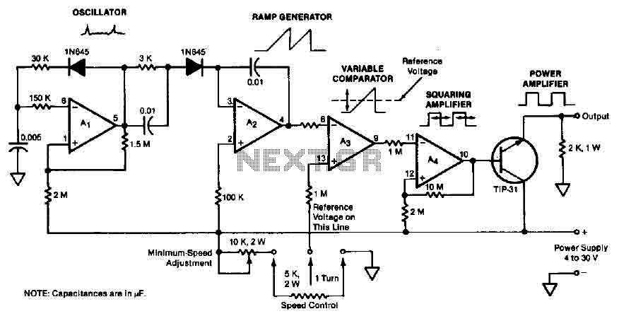
The quad operational amplifier circuit provides a pulse width modulation control ranging from 0 to 100 percent. The controller utilizes an LM3900 and operates with a single supply voltage between 4 to 30 V. A 1 kHz oscillator amplifier,...