
Motor control with tachometer
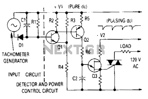
The described circuit utilizes a generator output that undergoes rectification and filtering to create a stable voltage supply for the base of a detector transistor. This configuration is crucial for regulating the speed of a motor based on feedback from a tachometer. The negative voltage generated plays a vital role in controlling the base voltage of the detector transistor, which is integral to maintaining the desired motor speed.
When the tachometer output indicates that the motor speed is lower than the set point, the detector transistor activates, turning on transistor Q2. This action leads to a rapid charging of the timing capacitor associated with the unijunction transistor. The unijunction transistor serves as a timing element in this circuit, and its operation is directly influenced by the charging rate of its timing capacitor.
As the tachometer voltage increases and approaches the desired level, the base-emitter voltage of transistor Q1 is reduced. This reduction in voltage effectively brings Q1 closer to its cutoff point, decreasing the collector current that charges the timing capacitor. The slower charging of the capacitor results in a delay in triggering the thyristor, which is responsible for controlling the power delivered to the motor.
The overall effect of this feedback mechanism is to modulate the average power supplied to the motor. By adjusting the timing of the thyristor's activation based on the motor speed feedback, the circuit ensures that the motor receives just enough power to maintain its speed without overshooting the desired set point. This form of control enhances the efficiency of the motor operation and contributes to the longevity of the system by preventing excessive power delivery.The ^generator output is rectified then filtered and applied between the positive supply voltage and the base of the detector transistor. This provides a negative voltage which reduces the base-voltage when the speed increases. In normal operation, if the tachometer voltage is less than desired, the detector transistor is turned on, then turns on Q2 which causes the timing capacitor for the unijunction transistor to charge quickly.
As the tachometer output approaches the voltage desired, the base-emitter voltage is reduced to the point at which Ql is almost cut off. Thereby, the collector current which charges the unijunction timing capacitor is reduced, causing that capacitor to charge slowly and trigger the thyristor later in the half cycle. In this manner, the average power to the motor is reduced until just enough power to maintain the desired motor speed is allowed to flow.
🔗 External reference
Related Circuits
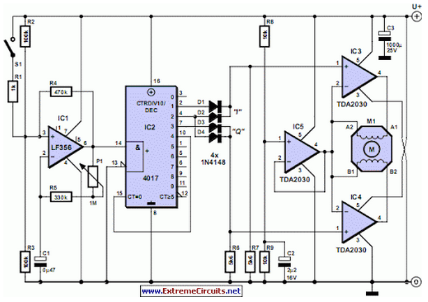
Stepper motors are available in several versions and sizes with a variety of operating voltages. The advantage of this general-purpose controller is that... Stepper motors are electromechanical devices that convert electrical energy into precise mechanical movement. They are widely used...
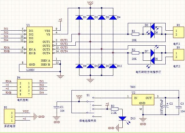
1. Driver: L298N Dual H Bridge DC Motor Driver IC 2. Supply voltage for the driven part (Vs): +5 V to +35 V; for internal board power supply, Vs: +7 V to +35 V 3. Peak current for the...
The motor control circuit depicted in the image utilizes the LM339 comparator among other components. When the input control signal is high (PWL), comparators A and A3 activate the power amplifier circuit, which consists of A4, VT5, and VT6,...
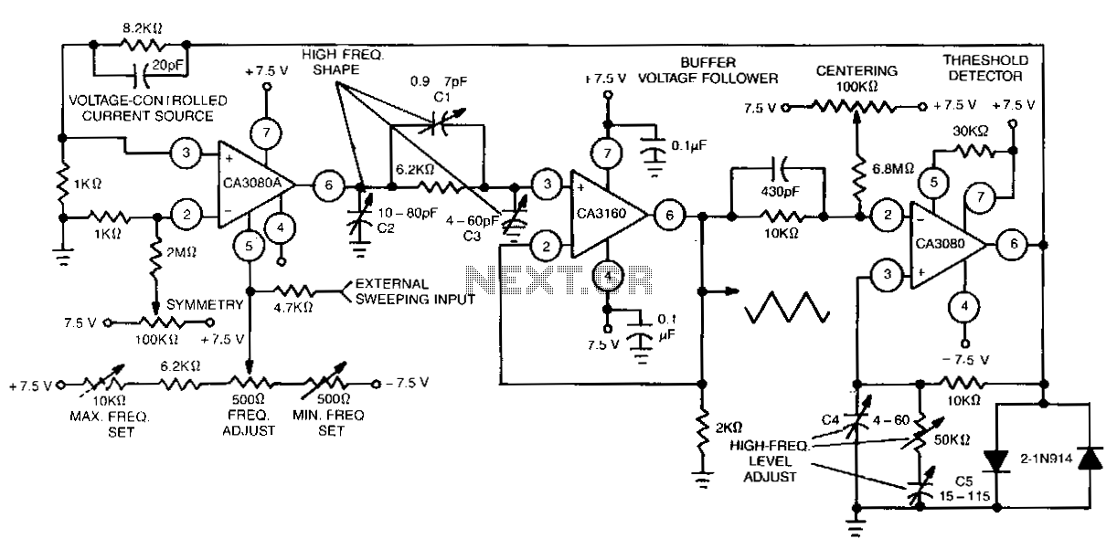
This function generator features an adjustment range exceeding 1,000,000 to 1 and utilizes a CA3160 BiMOS operational amplifier as a voltage follower. It incorporates a CA3080 operational transconductance amplifier (OTA) as a high-speed comparator, alongside another CA3080 configured as...
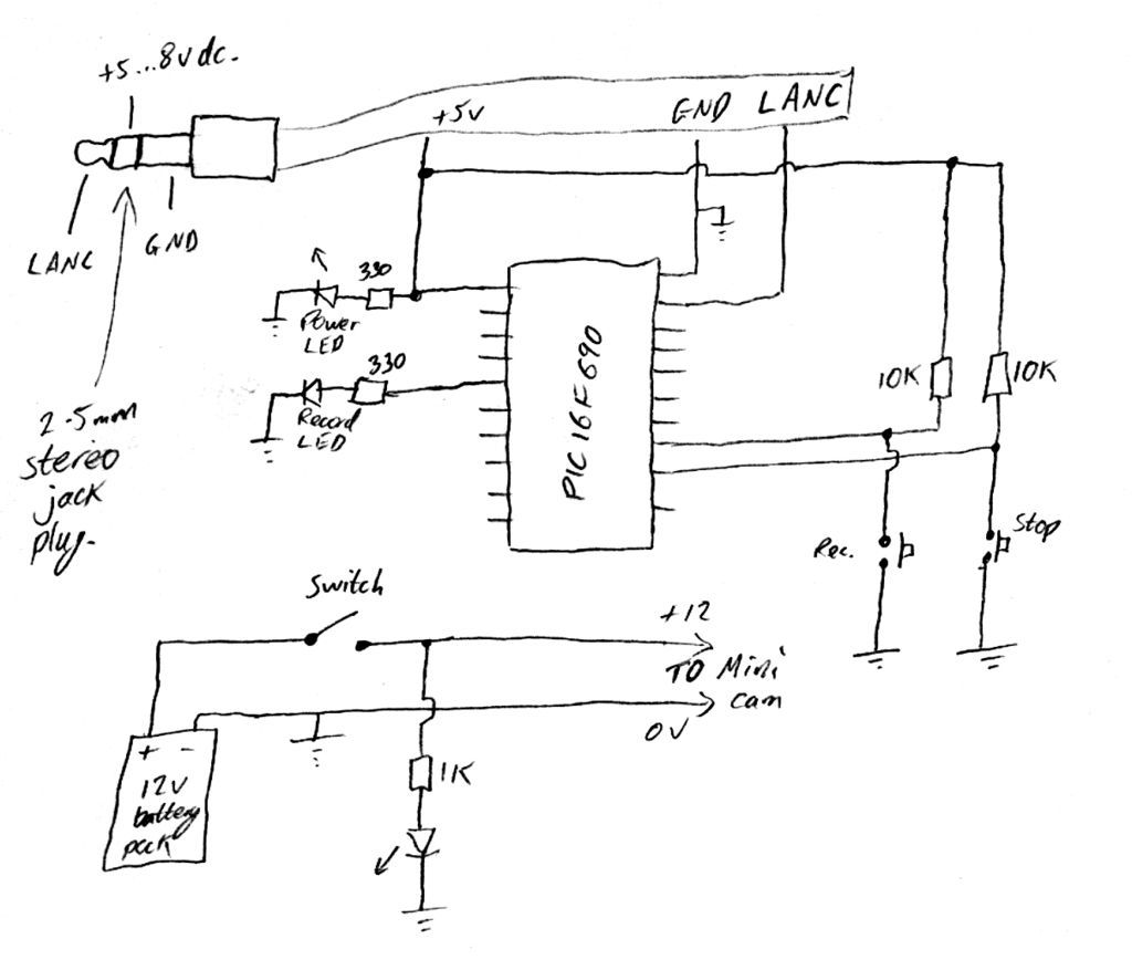
Inexpensive PIC-controlled helmet camera utilizing Sony LANC, suitable for extreme sports. This guide will demonstrate how to create an affordable helmet camera. The proposed electronic schematic involves a PIC microcontroller interfaced with a Sony LANC (Local Application Control Bus) to...
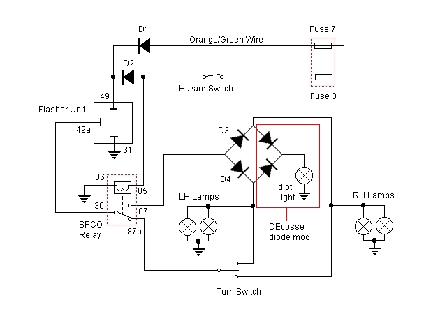
For some time, there has been a desire to incorporate a hazard flasher system into the Bonneville SE. After reviewing various discussions on this topic, a unique add-on system has been developed that functions correctly as hazard lights. This...
Warning: include(partials/cookie-banner.php): Failed to open stream: Permission denied in /var/www/html/nextgr/view-circuit.php on line 713
Warning: include(): Failed opening 'partials/cookie-banner.php' for inclusion (include_path='.:/usr/share/php') in /var/www/html/nextgr/view-circuit.php on line 713