
Motor controller with Analogue Opto Isolator

The circuit described utilizes an opto isolator to safely transfer an analogue signal while maintaining linearity and simplicity. The design aims to connect a mains-driven thyristor motor controller with low voltage analogue circuits, ensuring that any high voltage risks from wiring faults or component failures are mitigated.
Key components include transistors (Tr1, Tr2, Tr3) configured as a precision current mirror, which plays a crucial role in establishing a controlled current flow. The mirror's operation is initiated by a voltage applied to the input (Vin), which generates a corresponding 'mirror' current that is directed into the collector of Tr3. The opto isolator's transmitter responds to this current, activating its internal transistor to facilitate signal transfer.
The circuit's feedback mechanism is highlighted by the interaction between Tr11, D5, and capacitor C6. When the opto isolator is activated, Tr11 is turned off, causing D5 to reverse bias and allowing C6 to charge through R37. This configuration maintains the opto isolator's conduction for a specified duration. Once C6's charge diminishes below a certain threshold, Tr11 reactivates, discharging C6 rapidly through D4 and D5, enabling short intervals between pulses.
The output voltage (Van) is directly influenced by the frequency of the input signal; as the input voltage increases, the frequency of the opto pulses becomes more frequent, leading to a higher average output voltage. This design ensures that the motor controller responds to the averaged voltage rather than individual pulses, which is essential for stable operation.
Additionally, the circuit incorporates capacitors such as C1 (4n7), which initially remains uncharged. The current from the current mirror influences the voltage at Tr5's base, determining the conduction state of Tr4 and subsequently controlling Tr6 and Tr9. The positive feedback loop involving C3 ensures that once Tr9 is activated, it continues to draw current, reinforcing its conduction and driving the output through the opto-coupled diode D3.
This circuit effectively combines isolation, linearity, and feedback control, making it suitable for applications involving thyristor motor controllers and low voltage analogue systems, while also addressing the potential noise generated by these components.This is a circuit to use a standard, low quality opto isolator to transfer an analogue signal with reasonable linearity and without complicated feedback loops to monitor and linearise it. The circuit was designed to interface a mains driven thryristor motor controller to low voltage analogue circuitry.
In this application you could isolate the thyristor controller with a transformer and earth one side of the motor, but you still have a potentially high voltage situation if there is a wiring fault or component failure. Also motors and thyristor controllers are potentially good generators of noise: in a system which used several motor controllers it was considered essential to isolate the input signal! Thyristor motor controllers, without lots of setting up and without tachogenerator feedback can give around 15:1 speed range.
This isolator was certainly linear enough for this sort of application and performed very well in a production situation. It may be instructive to compare the first part of this circuit with the voltage controlled clock generator.
You may notice a distinct resemblance in overall form. Tr1, Tr2 and Tr3 form a precision current mirror (see also Current sources and mirrors - a voltage applied to Vin causes current to flow through R1 and R2 giving rise to a 'mirror' current which is sinked into Tr3's collector. The pulse in the opto coupler's transmitter causes its transistor to conduct. The original circuit worked very reliably on a cheap coupler such as 4N38. When the opto conducts, Tr11 turns off, D5 goes reversed biased and C6 charges up thorough R37, holding the opto coupler on for a defined pulse time.
As soon as C6's current falls too low to maintain conduction, Tr11 turns on again, discharging C6 via D4,and D5. This discharge path is low impedance so discharges C6 very quickly. The circuit can therefore work with a very short time between pulses. Clearly, is the pulse is 90% of the duty cycle, the average voltage on Van is 95% of the supply voltage.
At low input voltages (into Vin) the oscillator charging current will be low and the opto pulses widely spaced. Tr11 will be conducting most of the time therefore and the average output voltage, Van, will be low. As the oscillator's frequency increases with increasing input voltage, pulses will be more frequent and the average output voltage will rise.
The voltage on Van is always a fixed pulse width at variable frequency: the motor controller it was used with had a ramp (as do pretty well all motor controllers) which averaged out this pulse train so the controller responded only to the average voltage. Consider C1 (4n7) at first uncharged. The current sinked by the mirror changes it and the base of Tr5 falls. When the base voltage of Tr5 is near the positive line, Tr4 is conducting but when it falls to about 9.15v below the +ve line (voltage determined by D2), Tr5 starts to cut off and Tr6 starts to conduct.
This will turn on Tr9, whose collector voltage is coupled back to Tr6's base via C3 to cause positive feedback so Tr9 turns hard on, drawing a pulse through C4 and the opto-coupled diode, D3. 🔗 External reference
Related Circuits
The LA1061M is an antenna switching controller designed for mobile radio equipment. It utilizes several inputs from the receiver circuitry to choose between the main antenna and a sub-antenna based on signal strength and quality. Weak and strong signals...
An IR remote control is a widely used device found with televisions, VCRs, and home theaters. It can also be utilized to control personal devices such as lights and air conditioning. Remote controls operate using infrared (IR) light, which...
A servo is a compact motor capable of precise positioning at various angles. It incorporates internal circuitry designed to maintain its position automatically. A servo motor typically consists of a DC motor, a gear system, a potentiometer, and a control...
The circuits on this page are for motor controls using Push buttons and would typically be found in commercial and industrial installations. The circuits do not show the wiring of the motors themselves as this depends on the particular...
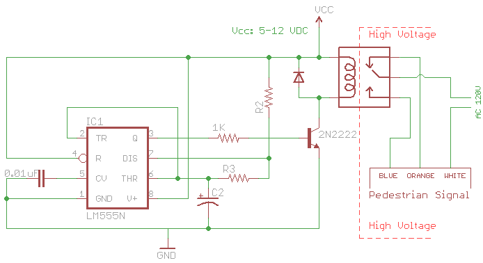
The signal consists of three wires: common, "walk," and "don't walk." This document outlines the operation of the unit's countdown feature. The information and examples provided here are applicable to other models and brands of signals. The signal was...
This integrated circuit is highly efficient and does not require any external glue logic for operation. It features two pins to control a motor: one for direction and the other for stepping pulse triggers. The design is compact and...