
IR remote control signal receiver using AVR microcontroller

The following code snippet demonstrates the implementation of an IR remote control receiver using the TSOP1736 chip. The pin connected to the TSOP1736 is defined as K1:
```c
#define K1 (1<<PINA0)
uint8_t impulse_prev = 0;
uint8_t counter_impulse_1 = 0;
uint8_t flag_rx = 0;
uint8_t counter_impulse_0 = 0;
uint8_t impulse = 0;
uint64_t counter_ik = 0;
uint64_t code = 0;
ISR(TIMER0_OVF_vect) {
uint8_t c;
uint8_t str[35];
uint64_t i;
// Timer0 initialization
TCNT0 = 0xFF;
// Invert input signal
if (K1 == 1)
impulse = 0;
else
impulse = 1;
if ((impulse_prev == 0) && (impulse == 1)) { // Rising edge detection
// Reset counter
counter_impulse_1 = 0;
if ((counter_impulse_0 > 3) && (flag_rx == 1) && (counter_impulse_0 < 23)) {
// If receiving symbols
if (counter_impulse_0 > 12) // Logical 1 received
code |= (1 << counter_ik);
counter_ik++;
}
}
if ((impulse == 1) && (counter_impulse_1 < 50) ) // Counting positive pulses
counter_impulse_1++;
if ((impulse_prev == 1) && (impulse == 0)) { // Negative front
counter_impulse_0 = 0;
if (counter_impulse_1 > 30) { // One long sync pulse
code = 0;
counter_ik = 0;
flag_rx = 1;
}
}
if ((impulse == 0) && (flag_rx == 1) && (counter_impulse_1 < 150)) // Counting negative pulses
counter_impulse_0++;
if ((counter_impulse_0 > 50) && (flag_rx == 1) && (impulse == 0)) { // End of receive
flag_rx = 0;
counter_impulse_0 = 0;
counter_impulse_1 = 0;
counter_ik = 0;
code = 0;
}
impulse_prev = impulse;
}
```
The interrupt service routine `ISR(TIMER0_OVF_vect)` is triggered at a frequency of 10.8 kHz, which is sufficient to capture the pulse frequency of the received code. Initially, the input signal is inverted, and the current signal level from the photo-sensor is stored in the variable `impulse`. The duration of positive and negative impulses is tracked using `counter_impulse_0` and `counter_impulse_1`, which measure the elapsed time since the signal front was detected. The code corresponding to the remote control button is stored in the EEPROM and can be programmed by pressing the remote control button 20 times. If the button is missed, the process can be restarted from 0 to 20. An optional RS232 interface allows for the expansion of the remote switch's functionality by connecting it to another embedded platform or PC. The circuit transmits code in ASCII format at a speed of 1 kB/s. This implementation provides a foundational understanding of using a remote control with embedded platforms, with potential for further enhancements and adaptations.IR remote control is a device you can find everywhere where you can find TV, VCR or home theatre. Why not to use one of them for controlling your own devices like light, air conditioning etc. As we know remote control devices uses IR light. This is invisible light about 950nm wavelength. One biggest problem in using IR light is that there many oth er sources of it like sun, light bulbs, fire. In order to exclude other sources, IR signal is modulated by some frequency. Receiver has to be tuned for this frequency. Mostly remote controls transmit IR signal using 36kHz frequency signals. Transmitting and coding is one part which can be done more easily than receiving and decoding. Decoding is usually performed by using microcontrollers. Firs of all receiver has to get rid of 36kHz carrier frequency. This is not simple task to demodulate signal, this is why special IR receiver IC`s are produced. One of them is TSOP1736: this receiver simply removes 36KHz carrier signal and gives clean pulses that are used for device control. I won`t go too deep in how it works you can find this information in datasheets. This module is convenient to connect to microcontrollers like AVR or PIC, because it forms TTL signal levels compatible to them.
Pulse-distance modulations is commonly used by LG, JVC, Acorp, Hitachi, Nokia, Aiwa, Akai, AverMedia, NEC. So further we will discuss only this modulation type. As you have noticed pulse-distance modulation uses fixed length pulses while gap defines weather it is 1 (long gap) or 0 (short gap) logical value.
When using Pulse-Distance modulation firs goes LSB then MSB bits. If remote control button is pressed for a long time, then it sends one full packet and then after som time continuously sends unitary pulses informing that button is still pressed. Note, that different manufacturers may use different length of pulses. //pin connected to TSOP1736 #define K1 (1<
They show how much time have passed since signal front was registered. Remote control button code is stored in EEPROM. It can be programmed by pressing remote control button 20 times. After this code is saved to EEPROM. If you missed button then start again from 0 to 20. RS232 interface is optional if you want to expand functionality of remote switch by connecting it to another embedded platform or PC. Circuit sends code in ASCII format at kB/s speed. Of course it is easy to construct algorithm to another AVR MCU and for different purposes. This article only gives an idea of using a remote control with embedded platforms. We aim to transmit more information by carrying articles. Please send us an E-mail to wanghuali@hqew. net within 15 days if we are involved in the problems of article content, copyright or other problems.
We will delete it soon. 🔗 External reference
Related Circuits
Create an H-Bridge for controlling a DC brushed motor using PWM. One bridge will control one DC motor. The bridge will have three inputs: A, B, and PWM. Inputs A and B will determine the direction of the motor,...
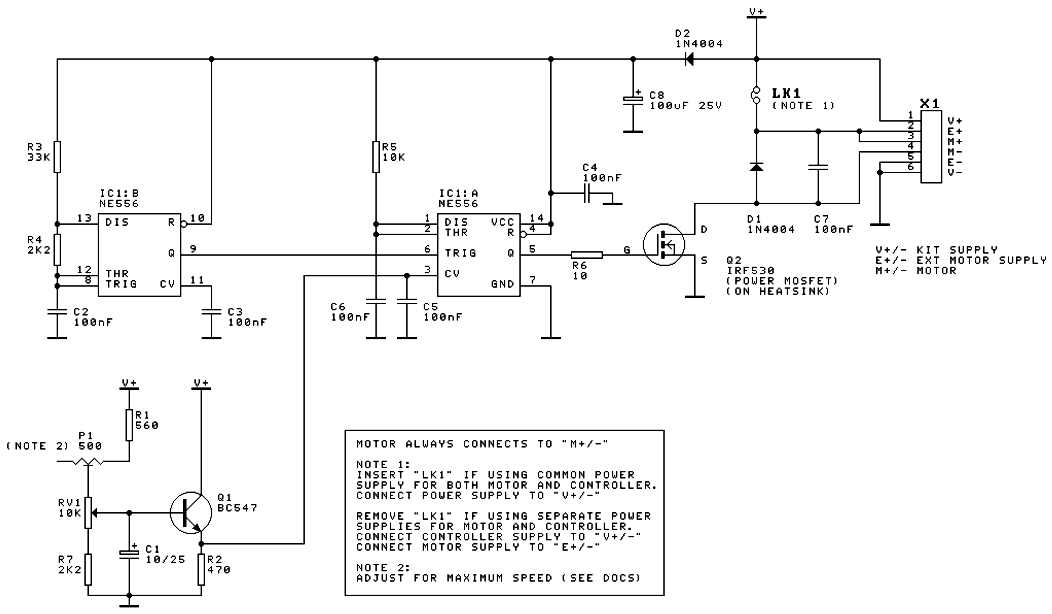
A DC motor speed controller circuit utilizes two timers configured as a Pulse Width Modulator (PWM). The integrated circuit employed for this purpose is the NE556, which is a dual timer/oscillator using NMOS technology. The DC motor speed controller circuit...
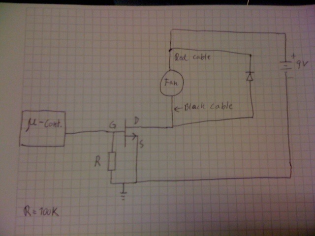
Control a fan using an LM34 temperature sensor and a computer fan with model number ASB0912L. A 2N7000 MOSFET transistor is utilized as a switch. The fan is intended to operate at a 35% duty cycle when the temperature...
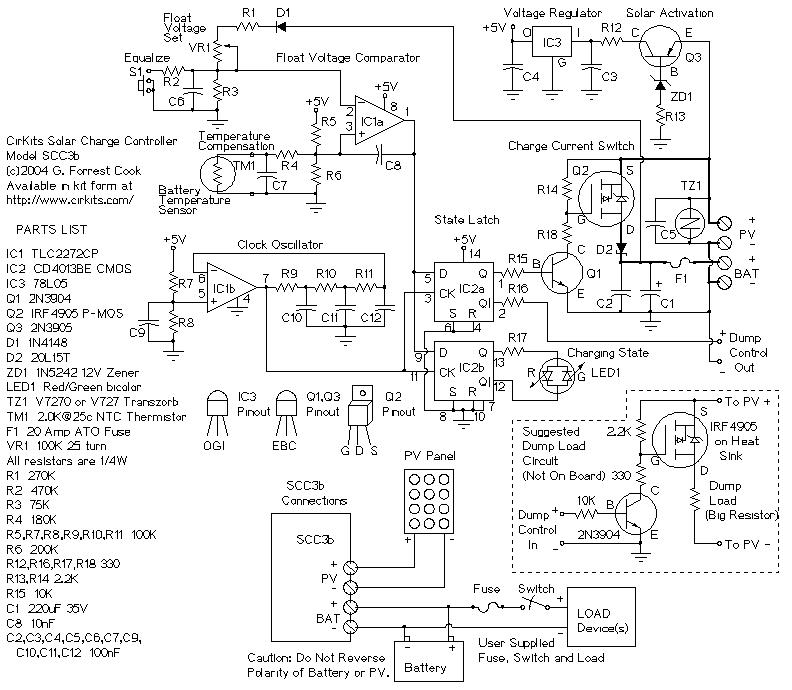
SCC3 12 Volt 20 Amp Solar Charge Controller. A kit with the circuit board and parts for this circuit is available from CirKits. SCC3 - 12 Volt 20 Amp Solar Charge Controller (C) G. Forrest Cook June. The SCC3 Solar...

The proposed remote control circuit can be utilized to control any electrical device within a range of 100 meters. This concept involves modifying an existing remote bell unit circuit, making the process straightforward. However, the construction aspect necessitates electronic...
Figure 2-32 (a) illustrates the time control diagram for a motor operated by switch S1. When S1 is set to position 1, the power driver circuit supplies current to the motor, enabling it to run. When S1 is switched...