
Motor Generator Stepper
The described circuit utilizes the 4017 decade counter IC, which operates by counting the pulses received from a clock signal. The counter outputs are utilized to generate the necessary phase-shifted signals for the stepper motor. The inverting OR gates play a crucial role in ensuring that the outputs are correctly phased for the operation of the motor. The circuit's design inherently limits the frequency output due to the division by four, necessitating an adjustment in the input frequency to maintain the desired motor speed.
The timing sequence for the stepper motor is critical for its operation, as it determines the direction and smoothness of the motor's movement. The transitions between the different states of the windings must be executed in a precise order to prevent stalling or erratic behavior. The connection of the reset pin to output 4 ensures that the counter cycles through its states in a continuous loop, allowing for sustained operation.
To drive a stepper motor effectively, a dedicated driver circuit is essential. This circuit typically employs transistors or MOSFETs to handle the higher current requirements of the motor, allowing it to be controlled by the low-power signals generated by the 4017. The driver circuit interfaces with the motor windings and provides the necessary power to achieve the required torque and speed. The design of the driver circuit should consider the specifications of the stepper motor, including its rated voltage and current, to ensure optimal performance and prevent damage to both the driver and the motor.
In summary, the combination of the 4017 decade counter, inverting OR gates, and a suitable driver circuit forms a robust solution for controlling stepper motors, enabling precise movement and control in various applications.Stepper motors are a subject that keeps recurring. This little circuit changes a clock signal (from a square wave generator) into signals with a 90-degree phase difference, which are required to drive the stepper motor windings. The price we pay for the simplicity is that the frequency is reduced by a factor of four. This isn`t really a problem, s ince we just have to increase the input frequency to compensate. The timing diagram clearly shows that the counter outputs of the 4017 are combined using inverting OR gates to produce two square waves with a phase difference. This creates the correct sequence for powering the windings: the first winding is negative and the second positive, both windings are negative, the first winding is positive and the second negative, and finally both windings are positive.
Internally, the 4017 has a divide-by-10 counter followed by a decoder. Output 0` is active (logic one) as long as the internal counter is at zero. At the next positive edge of the clock signal the counter increments to 1 and output 1` becomes active. This continues until output 4` becomes a logic one. This signal is connected to the reset input, which immediately resets the counter to the zero` state.
If you were to use an oscilloscope to look at this output, you would have to set it up very precisely before you would be able to see this pulse; that`s how short it is. The output of an OR gate can only supply several mA, which is obviously much too little to drive a stepper motor directly.
A suitable driver circuit, which goes between the generator and stepper motor. 🔗 External reference
Related Circuits
To sense and control the current in stepping motors and other similar devices, a linear integrated circuit such as the L6506 can be utilized. This chip set enables the formation of a constant current output. The L6506 is a versatile...
The battery packs were approximately $60 per pair, including a charger and batteries, and feature a three-bar battery gauge. Through experimentation, it was found that a voltage greater than 4.28V activates all three bars, while a voltage above 3.47V...
A Georgia Republic inventor, Tariel Kapanadze, claims to have invented a 5 kilowatt free energy generator. In a demonstration video, the device appears to produce copious amounts of energy from no visible source. More: The components apparently include a...
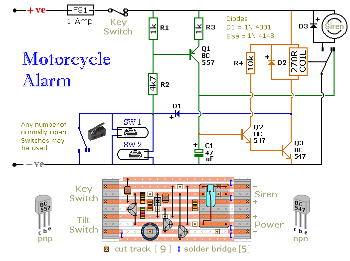
The circuit board and switches require protection from environmental factors, as moisture or condensation can lead to malfunctions. The board is compact without its terminal blocks. It is advisable to select a siren that has sufficient internal space for...
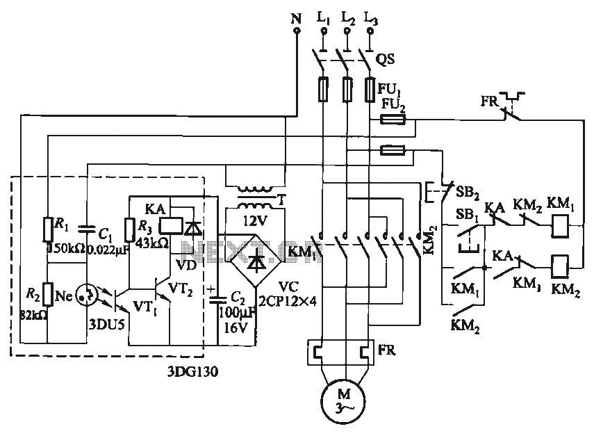
In certain applications, it is crucial to allow a motor to operate in only one specific direction, even when the power supply phase sequence is incorrect. This situation may arise due to external factors, such as incorrect wiring after...
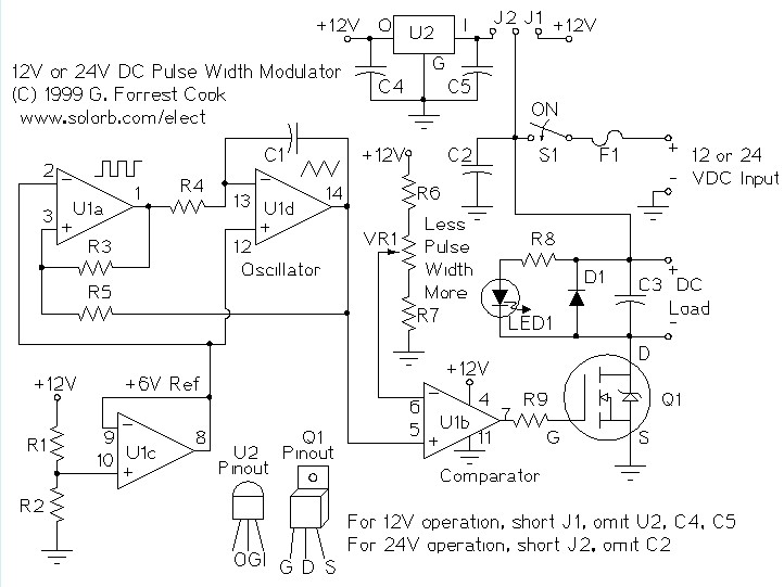
A pulse width modulator (PWM) is a device that can be utilized as an efficient light dimmer or DC motor speed controller. The circuit described here is intended for general-purpose applications, capable of controlling DC devices that draw up...