
Motor speed controller
The circuit described employs a 555 timer (IC1) configured in astable mode to generate a continuous series of clock pulses. These pulses serve as the timing signal for the subsequent counter circuits. The frequency of the 555 timer is determined by the values of resistors R1, R2, and capacitor C1, which can be adjusted to set the desired timing intervals for fan speed control.
The clock pulses produced by IC1 are directed to two counters: IC2, which is a decade counter (divide-by-10), and IC3, which is a divide-by-9 counter. The output from IC3 is critical, as it determines the operational phases of the fan. The configuration of R1, R2, and C1 is such that the outputs Q0 and Q1 of IC3 transition after approximately eight hours, indicating the time period for which the fan should operate at different speeds.
Initially, the output Q0 of IC3 is high, which activates transistor T1. This transistor functions as a switch that controls the relay RL1, allowing the fan or cooler to operate at full speed. As time progresses and the output Q1 becomes high, the fan speed is reduced to a medium setting. Eventually, after the complete timing cycle, both outputs will transition low, which deactivates the transistor and subsequently the relay, turning off the fan or cooler entirely.
Diodes D1 and D2 are employed to ensure that the outputs from IC3 do not interfere with each other, effectively ORing the signals to provide a stable control signal to the transistor base. This design allows for an automated control of the fan speed, adapting to the cooling needs as the ambient temperature drops and the user's metabolic rate decreases during sleep.
The connection of the device to the fan or cooler is illustrated in accompanying figures, which provide a clear schematic for practical implementation. This circuit not only enhances comfort during hot summer nights but also reduces the need for manual adjustments, thereby improving user convenience.During summer nights, the temperature is initially quite high. As time passes, the temperature starts dropping. Also, after a person falls asleep, the metabolic rate of one's body decreases. Thus, initially the fan/cooler needs to be run at full speed. As time passes, one has to get up again and again to adjust the speed of the fan or the cooler.The device presented here makes the fan run at full speed for a predetermined time. The speed is decreased to medium after some time, and to slow later on. After a period of about eight hours, the fan/cooler is switched off.Fig. 1 shows the circuit diagram of the system. IC1 (555) is used as an astable multivibrator to generate clock pulses. The pulses are fed to decade dividers/counters formed by IC2 and IC3. These ICs act as divide-by-10 and divide-by-9 counters, respectively. The values of capacitor C1 and resistors R1 and R2 are so adjusted that the final output of IC3 goes high after about eight hours.The first two outputs of IC3 (Q0 and Q1) are connected (ORed) via diodes D1 and D2 to the base of transistor T1. Initially output Q0 is high and therefore relay RL1 is energised. It remains energised when Q1 becomes high. The method of connecting the gadget to the fan/cooler is given in Figs 3 and 4. 🔗 External reference
Related Circuits
Carefully examine the following circuit diagram and attempt to construct the circuit on a breadboard first. If it functions correctly, proceed to create its PCB version. The circuit diagram serves as a blueprint for constructing an electronic circuit on a...
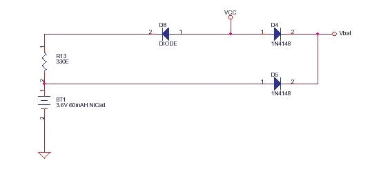
This circuit functions as a low-cost battery backup solution for SRAM and microcontroller/microprocessor applications. It utilizes 1N4148 diodes to prevent battery discharge back to the power source. Diode D8 provides a one-way path for charging the battery through resistor...
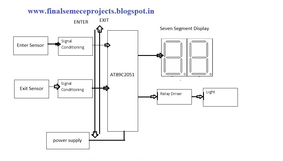
This project involves an automatic room light controller with a bidirectional visitor counter using a microcontroller. It is designed to manage room lighting and accurately count the number of individuals present. When a person enters the room, the counter...
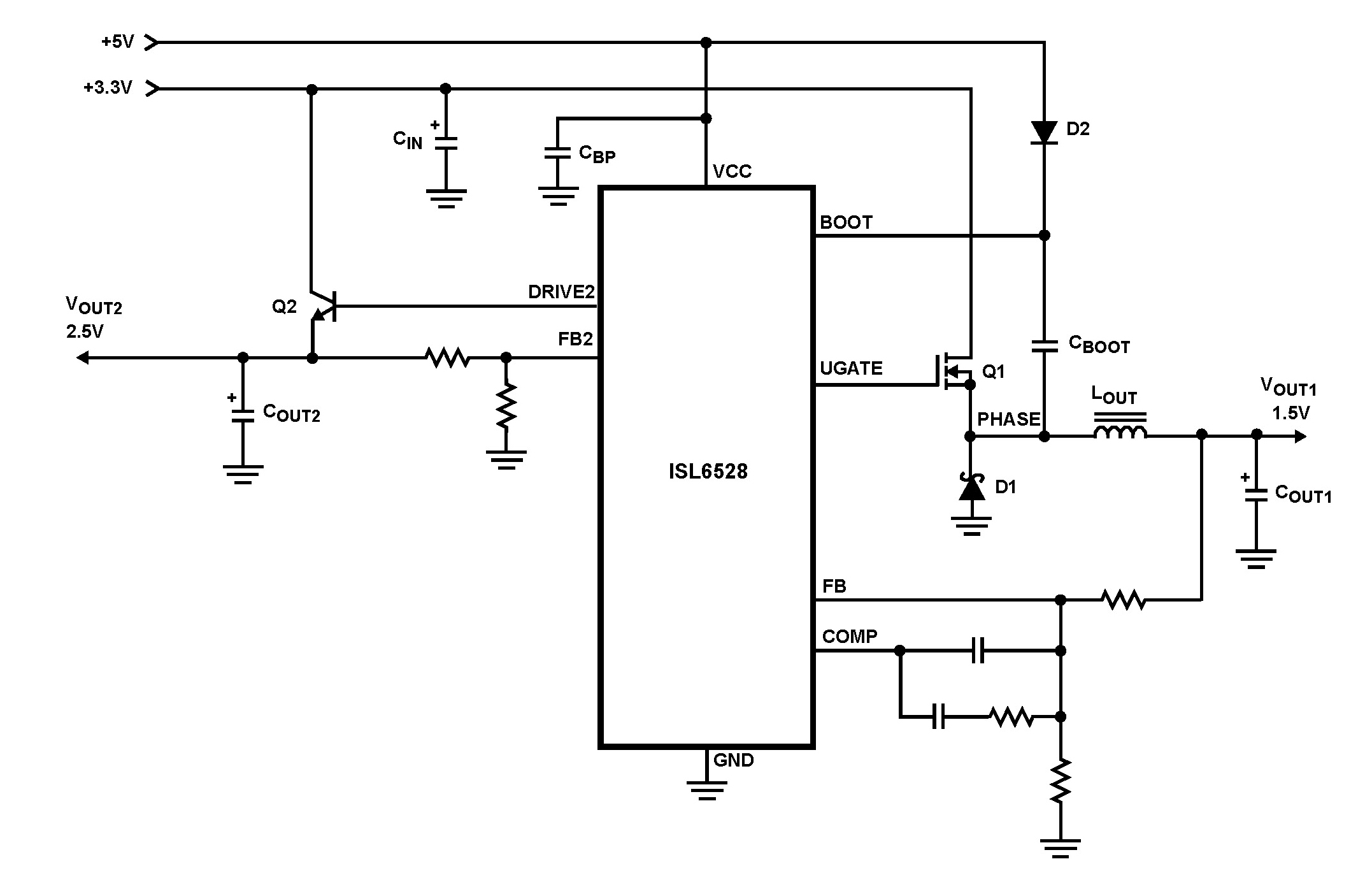
The ISL6528 offers power control and protection for two output voltages in high-performance graphics cards and other embedded processor applications. This dual-output controller drives an N-Channel MOSFET in a standard buck topology and an NPN pass transistor in a...
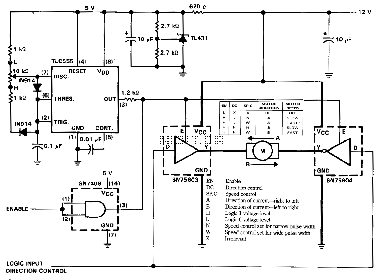
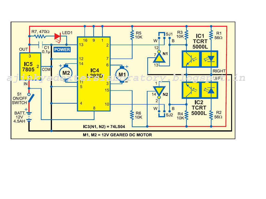
The figure illustrates a reversible DC motor drive application with adjustable speed control. The D inputs for these drivers are complementary and can be tied together and driven from the same logic control for bidirectional motor drive. The enables...

The trembler (motion-activated) switch triggers an alarm for 5 seconds before automatically turning off. The circuit has a timeout period of 10 seconds to allow the trembler switch to stabilize. The trembler switch circuit operates by detecting motion through a...
Warning: include(partials/cookie-banner.php): Failed to open stream: Permission denied in /var/www/html/nextgr/view-circuit.php on line 713
Warning: include(): Failed opening 'partials/cookie-banner.php' for inclusion (include_path='.:/usr/share/php') in /var/www/html/nextgr/view-circuit.php on line 713