
LINE TRACER ROBOT WITHOUT MICROCONTROLLER

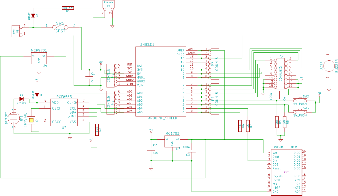
The circuit diagram serves as a blueprint for constructing an electronic circuit on a breadboard, which is a temporary platform for prototyping and testing. The initial step involves analyzing the schematic to understand the arrangement of components, their connections, and the overall functionality of the circuit.
Once the circuit is assembled on the breadboard, it is crucial to verify its performance by applying power and testing the output against expected results. This may involve measuring voltages, currents, and signal integrity using appropriate test equipment such as multimeters or oscilloscopes. If the circuit operates as intended, the next phase involves designing a printed circuit board (PCB) layout.
Creating a PCB version requires translating the breadboard layout into a schematic design software, where the circuit connections are optimized for a compact and efficient layout. The PCB design must include considerations for trace widths, component placement, and the routing of power and signal paths to minimize interference and ensure reliability. After finalizing the design, the PCB can be fabricated, allowing for a more permanent and robust implementation of the circuit.
This process emphasizes the importance of thorough testing and verification at each stage to ensure the circuit's functionality and reliability in its intended application.Now Look carefully following circuit Diagram & try out the circuit on bread board first. if it is working properly go to making its PCB version. the P.. 🔗 External reference
Related Circuits
The circuit automatically lights a bulb upon the arrival of a telephone ring and simultaneously mutes the audio from the music system or TV while the telephone handset is off-hook. The lighting of the bulb not only indicates an...
This simple robot responds to light and avoids obstacles without the need for a microcontroller, programmer, or PC. The primary component in the circuit is a window discriminator, which functions as an advanced window comparator. Resistors R1 and R2,...
This circuit is designed to serve as a programmable LED display for various applications. It features an 8 x 32 LED dot matrix interfaced with a Xino (or Arduino). In addition to the display, the circuit includes two buttons...
This simple circuit generates narrow pulses at about 700-800Hz frequency. The pulses, containing harmonics up to the MHz region, can be injected into audio or radio-frequency stages of amplifiers, receivers and the like for testing purposes. A high-pitched tone...

This circuit utilizes a sync-generator chip, a counter, and a decoder to detect the horizontal sync pulse that occurs at the beginning of line 10 in field 1 of an NTSC television picture. This circuit can be employed to...
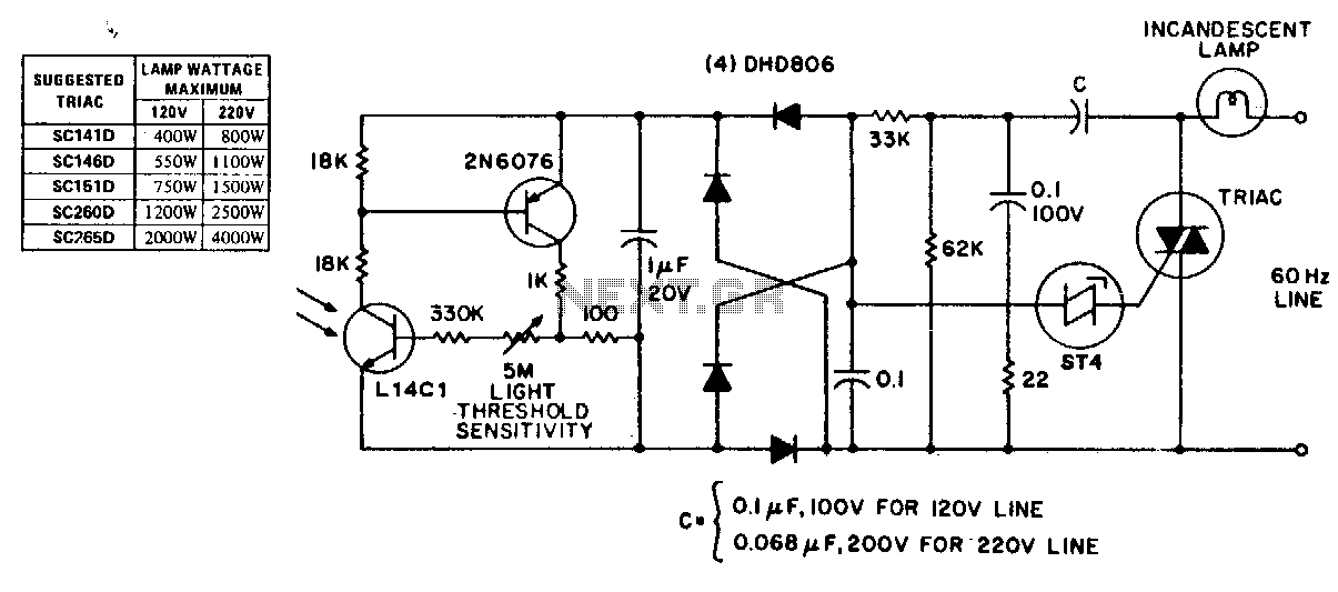
This circuit exhibits stable threshold characteristics based on the photo-diode current in the Ll4Cl, which generates a base-emitter voltage drop across the sensitivity setting resistor. The double phase shift network that supplies voltage to the ST-4 trigger ensures triac...