
motor timer

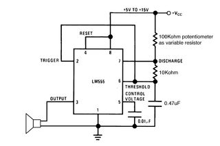
The described circuit utilizes a 555 timer in astable mode to control the operation of a small motor, which is responsible for rotating an ornament. The motor's rotation is transmitted through a monofilament line, creating a visually appealing effect as the ornament unwinds. The circuit's timing is primarily determined by the combination of the 1 megohm resistor and the 22 microfarad capacitor, which establishes a long charging time constant. This results in a delay of approximately 22 seconds for the motor to receive power, while the 555 timer's inherent characteristics reduce this to about 11 seconds for the output pulse duration.
The discharge path, governed by the 10 kilohm resistor, allows for quick discharging of the capacitor, thus enabling rapid activation of the motor. The choice of the TLC555 timer is advantageous due to its low power consumption and compatibility with lower voltage supplies, making it ideal for battery-operated applications. It is important to maintain a bypass capacitor in the circuit to ensure stable voltage levels and prevent glitches during operation, which can occur due to the internal switching of the timer.
The motor's performance may be influenced by the weight of the ornament, introducing friction that could hinder rotation. This aspect highlights the significance of ensuring that the power supplied to the motor is sufficient to overcome such mechanical resistance. If the current limitation is suspected to be the cause of reduced torque, adjustments such as modifying the circuit to eliminate unnecessary components, like a diode, or exploring alternate power sources could enhance performance.
The overall design is compact, allowing for assembly on perf board, where the leads from the capacitor and resistor serve as convenient points for connecting the motor and battery. This facilitates a straightforward construction process while ensuring that the circuit remains functional and efficient. Proper attention to component values and layout will lead to a reliable and effective motor control system for the ornament.The basic idea is to turn the motor just a little bit every 15 seconds or so. A monofilament line transmits the motion to the ornament. It gets wound by the motor and slowly unwinds by turning the ornament. The charging path has a 1 megohm resistor in it, which combined with the 22 microfarad capacitor, yields a time constant of about 22 seconds. The formula for the 555 timer has a factor of about 0. 5 on the time, so it comes out to around 11 seconds. The discharge path is through a 10 kilohm resistor, so its time constant is around a fifth of a second. During the discharge portion of the cycle, the 555 output pin is low; this is used to activate the motor.
Doing it this way takes advantage of the fact that the 555 can sink quite a bit more current than it can source (but read on, this didn`t work as we expected). In addition, it takes fewer components to implement a < 50 percent duty cycle. Use Google to search for 555 timer. We suggest using a TLC555 - it`s a low power version of the classic 555 and it runs reliably at 3 volts.
It also doesn`t glitch the power supply as badly as other kinds of 555 chips, which can happen when the internal flip-flop triggers. We tried skipping the bypass capacitor, but it didn`t work, so you`ll still need that. This circuit can be used with two AA batteries, or a 9 volt battery. It depends on the motor`s specifications. The 555 will accept anything from 3 to 18 volts; the timing won`t change. (But don`t panic! We found an answer. Read on. ) The weight of the ornament was probably increasing the friction. The theory is that the low power 555 was limiting the current to the motor, resulting in a loss of torque: completely shorting out the output to ground would let the motor work.
A simple fix might be to skip the diode or add another battery. Unfortunately we didn`t have room in the housing for another battery, so this began to appear to be a failed project. The layout can be used to build the timer on a piece of perf board. We used the leads on the big cap and the megohm resistor as a handy way to attach the extra wires needed for the battery and motor connections.
🔗 External reference
Related Circuits
NEC's UPB1008K is a Silicon RFIC specifically designed for handheld low-power, low-cost GPS receivers. The integrated circuit combines a low-noise amplifier (LNA) followed by a double-conversion RF/IF downconverter block and a phase-locked loop (PLL) frequency synthesizer on a single...
A DC drive for a universal motor is depicted in the figure below. To provide DC current to the motor, a diode bridge has been integrated around the motor. The motor... The schematic illustrates a DC drive system designed for...
A schematic arrangement for a two-quadrant controller is shown in the figure below. This figure illustrates the outer speed control loop and the inner current control loop. The tachogenerator derives the speed feedback signal; alternatively, an approximation of the...
Setting the 555 timer in astable mode results in a continuous series of output pulses. The 555 timer IC, when configured in astable mode, operates as an oscillator, generating a square wave output. This configuration does not require any...
A servo motor employs a servo mechanism, which is a closed-loop system that utilizes position feedback to accurately control the angular position of its shaft. Stepper motors, which operate as an open-loop system, can also achieve precise angular control,...
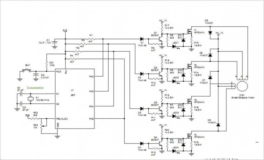
The following circuit illustrates a stepper motor controller based on the PIC16F84A integrated circuit. It features a transistor used for driving the motor. The stepper motor controller circuit utilizes the PIC16F84A microcontroller, which is a popular choice for controlling stepper...