
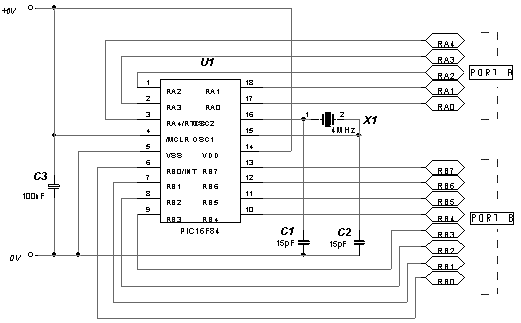
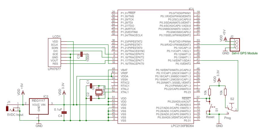
Stepper motor controller Based On The PIC16F84A IC

The stepper motor controller circuit utilizes the PIC16F84A microcontroller, which is a popular choice for controlling stepper motors due to its versatility and ease of programming. The microcontroller is responsible for generating the control signals required to drive the stepper motor in a precise manner.
In this configuration, the circuit typically includes a series of transistors that act as switches, allowing the microcontroller to control the power supplied to the motor coils. The transistors are connected to the output pins of the PIC16F84A, which sends PWM (Pulse Width Modulation) signals or logic high signals to turn the transistors on and off. This switching action enables the motor to step in discrete increments, allowing for accurate positioning and control.
The circuit may also include additional components such as resistors, capacitors, and diodes to protect the transistors from back EMF generated by the motor coils and to filter the signals. A power supply is essential to provide the necessary voltage and current for the stepper motor operation.
To ensure proper functionality, the microcontroller is programmed with a specific algorithm that dictates the sequence in which the transistors are activated. This sequence is crucial for determining the direction of the motor's rotation and the speed at which it operates. By adjusting the timing of the signals sent to the transistors, the motor can be controlled effectively for various applications, including robotics, CNC machines, and automation systems.
In summary, this stepper motor controller circuit demonstrates a practical application of the PIC16F84A microcontroller, showcasing its ability to manage motor control through a well-structured design and programming approach.The following circuit shows about Stepper motor controller. This circuit based on the PIC16F84A IC. Features: transistor is used to drive the . 🔗 External reference
Related Circuits
Understanding how to program the PIC microcontroller in theory is beneficial; however, practical learning occurs when the code is executed on a PIC within a circuit. One can either construct a new circuit for each test or utilize a...
The ArduinoISP Bootloader/Programmer Combination Shield (not displayed) works with an Arduino equipped with a USB to serial chip (e.g., Arduino Uno) to upload the bootloader and sketches to a DIYduino. A USB to Serial programmer can also be utilized...
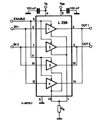
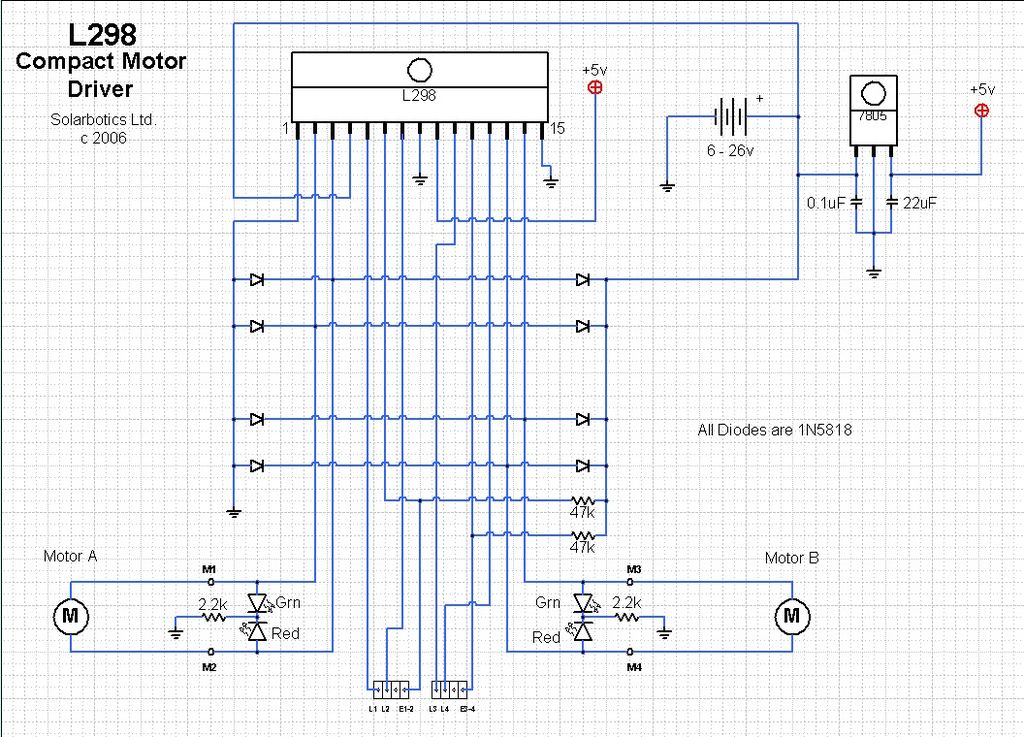
The L298 IC H-Bridge DC motor driver features two H-Bridge circuits, allowing it to control two DC motors simultaneously. Each H-Bridge can deliver currents up to 2A, but when used in parallel, the L298 can provide a total current...
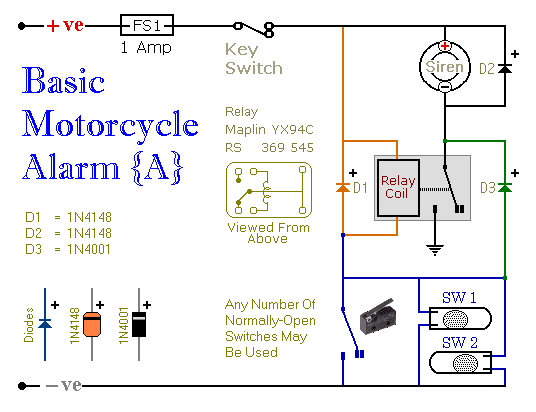
These are two easy-to-build relay-based alarms that can be used to protect motorcycles, among other applications. Using relays with 6-volt coils will safeguard a "Classic Bike." Both alarms are compact, with completed boards occupying approximately half a cubic inch...
In 1991, there was significant interest in a specific display technology that was difficult to find locally and expensive to import. Currently, this technology has become widely available and is considered obsolete due to the affordability and accessibility of...
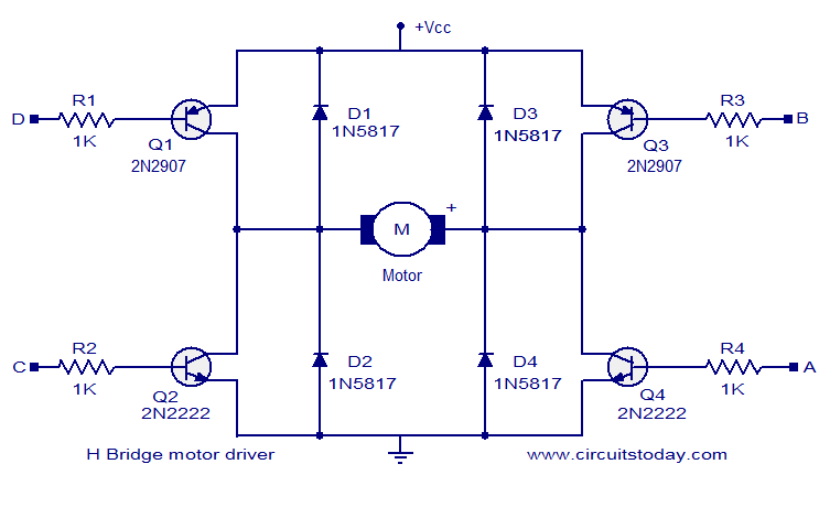
The circuit presented is a simple H-bridge motor driver circuit utilizing commonly available components. An H-bridge is an efficient method for driving motors and is widely used in various electronic projects, particularly in robotics. The circuit illustrated is a...