
Motorcycle 13.6V 3A charger
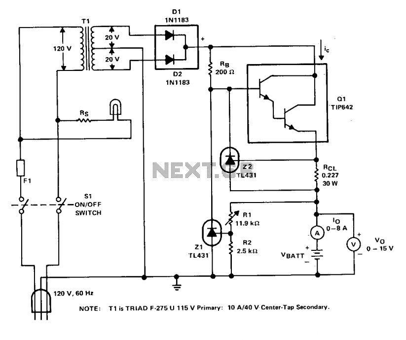
The described circuit functions as a battery charger, specifically designed for small batteries, with a maximum output current of 3A. The main components include the LM350 adjustable voltage regulator, which is responsible for maintaining a constant voltage output, and the LM1458 operational amplifier, which regulates the charging current.
The charging process begins with the LM350, which is configured to output a constant voltage of 14.1V for initial charging. This voltage is achieved by setting the reference voltage between points C and B to 1.25V. A 1K resistor is connected between point B and ground, enabling the adjustment of the output voltage. An additional 2K adjustable potentiometer is placed in series with the 1K resistor, allowing precise control over the output voltage.
As the battery begins to charge, current flows through a 0.1 ohm wire-wound resistor, generating a voltage drop that is monitored by the LM1458. The operational amplifier compares this voltage drop with the adjusted voltage from a 100-ohm potentiometer. If the voltage drop exceeds the set threshold, the LM1458 outputs a low signal, which in turn activates the BC558 transistor. This action reduces the charging current and initiates a trickle charge at 13.6V, which is safe for maintaining battery health without overcharging.
The circuit employs a feedback mechanism to stabilize the current. The combined resistance of the 2.2 ohm resistor, the 100-ohm potentiometer, and a 150-ohm resistor are connected to the non-inverting input of the LM1458. The inverting input is connected to the 0.1 ohm resistor. This configuration ensures that the LM1458 remains in a high state during normal charging conditions.
To protect the circuit, a 1N4001 diode is placed across the input and output, safeguarding the LM350 from potential damage due to voltage interruptions. The LM350 requires adequate heat dissipation; therefore, it should be mounted on a suitable heat sink to manage the thermal load effectively, with a thermal resistance rating of approximately 3.3°C/Watt.
The LM350 can be replaced with an NTE970, and the BC558B transistor can be substituted with an NTE159 for alternative component options. Overall, this circuit design provides a reliable and efficient method for charging small batteries while incorporating safety features to prevent overcharging.This 3A charger was originally designed to work with small batteries like those used in motorcycles. In principle it can be used to charge car batteries also but will take a lot longer.
The charger below charges a battery with a constant current to 14.1 volt. When this level is reached, the current charge drops automatically to a safer level (13.6V) and keeps charging at this slower rate untill the LED lights up indicating a fully charged battery.
This project looks very much alike with the Gel cell II charger elsewhere posted in the 'Circuits' section. The difference is the IC, namely a LM1458 instead of a LM301A. Nice job Jan! The LM350 is an adjustable voltage regulator and keeps the voltage between points C and B at 1.25 Volt. By adding a 1K resistor between point B and gnd (-) you can, as it were, lift up the output voltage.
To accurately control the output voltage we add to this resistor, in series, a 2K adjustable 10-turn potentiometer. As soon as a battery is connected a current flow occurs, controlled by the right halve of the LM1458.
The current through the 0.1 ohm resistor causes a voltage drop. This drop is compared with the voltage on the walker of 100-ohm pot. The moment this drop is greater than the one adjusted with the potmeter will cause the output of the LM1458 IC to go low and a small current starts to flow thru the diode and this in effect will reduce the current through the series resistors 1K + 2Kpot. The current is hereby stabilized. The point between C and B is devided by three resistors; 2.2 ohm, 100 ohm pot, and the 150 ohm. 2.2 ohm and the 100 ohm potmeter are connected to the non-inverting input (+) of the LM1458 IC. The inverting input (-) is connected to the 0.1 ohm wire-wound resistor in series with the output.
As long as the voltage drop, caused by the current-flow over this resistor is greater than the voltage drop over the 2.2 ohm resistor the output of the LM1458 will stay high and in turn block the BC558 transistor. But as soon as the charge current falls below a specific value the 1458 will go low and turn on this transistor which wich activate the LED.
At the same time a small current will flow thru the 'Rx' resistor, which will cause that the output voltage of the charger switches to 13.6 Volt. This is a very safe output voltage, and does not cause overcharging to the battery and remains fully charged (trickle).
The voltage regulator LM350 has to dissipate a lot of energy so make sure to mount it on a large cooling fin. (e.i. 3.3°C/Watt) Diode 1N4001 over the input/output is necessary to prevent damage to the regulator in case the input voltage gets interrupted.
The LM350 can be substituted with a NTE970, and the BC558B with a NTE159 if you wish. 🔗 External reference
Related Circuits
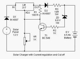
By adjusting the Adjust pin, the output voltage and current can be regulated. A variable resistor (VR) is connected between the Adjust pin and ground to achieve an output voltage of 9 volts to the battery. Resistor R3 limits...
The circuit is designed to be powered directly by a power supply, which is why it does not include a transformer, rectifier, or filter capacitors in the schematic. However, the addition of these components is possible. To operate the...
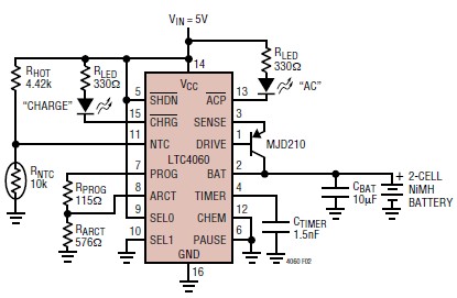
The LTC4060 integrated circuit can be utilized to create a straightforward smart NiMH battery charger electronic project. This charger circuit functions as a complete fast charging system for NiMH or NiCd batteries. It requires only a few external components...
The charger operates with a charging voltage of 2.4 V per cell, aligning with the recommendations of most manufacturers. The circuit delivers a charging voltage of 14.4 V (6 cells at 2.4 V per cell) in a pulsed manner...
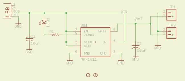
Lithium Polymer Batteries are a very common source of power today. Many electronics gadgets have one inside, and they have some reasonable features. I've bought great batteries, with different sizes and capacities for my electronics projects. So long I'm...
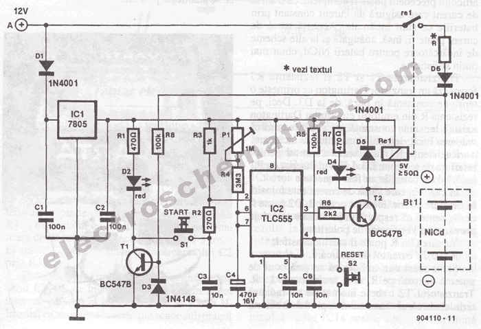
The portable battery charger has been designed to enable the charging of NiCd batteries outdoors using a 12 V vehicle battery. The portable battery charger is engineered to facilitate the charging of Nickel-Cadmium (NiCd) batteries in outdoor environments, leveraging the...
Warning: include(partials/cookie-banner.php): Failed to open stream: Permission denied in /var/www/html/nextgr/view-circuit.php on line 713
Warning: include(): Failed opening 'partials/cookie-banner.php' for inclusion (include_path='.:/usr/share/php') in /var/www/html/nextgr/view-circuit.php on line 713