
Motorcycle Alarm schematic
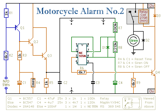
The described circuit is an automotive security system designed for motorcycles, incorporating an intermittent siren output and an automatic reset feature. The circuit can be activated through a key-switch or a concealed switch, providing flexibility in operation. Additionally, it has the capability to automatically engage when the ignition is turned off, enhancing security by ensuring the system is armed without user intervention.
The core of the design utilizes an Asymmetric Timer, which allows for customizable timing intervals for the siren output. This timer can be configured to generate an intermittent sound pattern, thereby drawing attention when unauthorized access is detected. The circuit can be expanded by integrating external relays, which can control various functions such as immobilizing the motorcycle or flashing the lights, thereby increasing the deterrent effect against theft.
The system supports the integration of multiple normally-open switches, which can be strategically placed to enhance security. For instance, tilt switches can be employed to detect movement of the motorcycle, such as when the steering is turned or when the bike is lifted off its side-stand or moved from its center-stand. This feature can trigger the siren if the motorcycle is tampered with. Additionally, micro-switches can be utilized to safeguard removable panels, ensuring that any unauthorized attempts to access critical components are immediately flagged by the alarm system.
The overall design emphasizes user convenience while maintaining a high level of security, making it suitable for motorcycle enthusiasts looking to protect their vehicles effectively. Proper installation and configuration of the switches and relays are crucial for optimal performance and reliability of the system.This circuit features an intermittent siren output and automatic reset. It can be operated manually using a key-switch or a hidden switch; but it can also be wired to set itself automatically when you turn-off the ignition. By adding external relays you can immobilize the bike, flash the lights etc. Ron has used my Asymmetric Timer as the basis for his design. Any number of normally-open switches may be used. Fit "tilt" switches that close when the steering is moved or when the bike is lifted off its side-stand or pushed forward off its centre-stand. Use micro-switches to protect removable panels and 🔗 External reference
Related Circuits
The circuit is designed to ensure that the headlights or side lights are automatically switched off after the ignition contact is turned off. This prevents the occurrence of a dead battery due to headlights being inadvertently left on. The circuit...
Approximately 20 years ago, small key-holders that emitted an intermittent beep for a few seconds upon detecting a whistle were quite common. These devices utilized a specialized integrated circuit (IC) that made them unsuitable for home construction. The current...
This document outlines a basic fire alarm circuit utilizing an LDR (Light Dependent Resistor) for fire detection. The circuit is designed to generate an audible alarm in response to smoke, which affects the LDR's resistance. In the absence of...

Dunlop Cry Baby Wah Wah Schematic. It is challenging to replicate the Cry Baby sound due to its unique characteristics. The Dunlop Cry Baby Wah Wah pedal is renowned for its distinctive tonal qualities and is a staple in many...
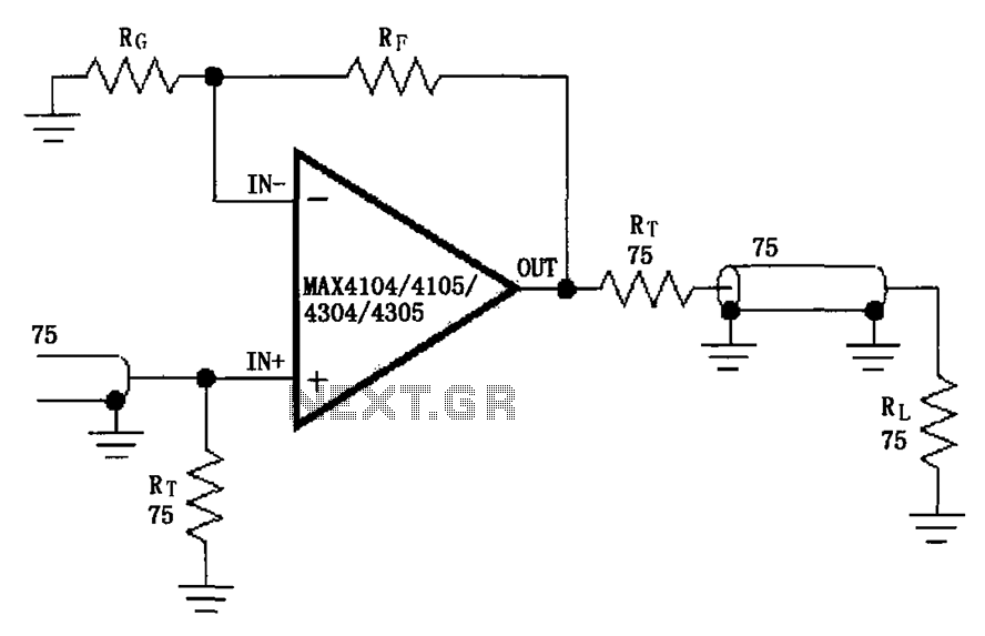
The circuit illustrated in the figure features a MAX4104/4105/4304/4305 video cable driver amplifier. This circuit is designed for use with coaxial transmission lines, optimizing the amplification of video signals to minimize reflections and maximize power transfer. The output impedance...
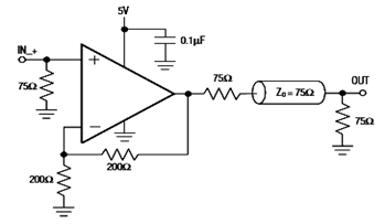
The diagram below illustrates a typical operating circuit for the video line driver using the IC4030/4031 schematic. It incorporates the MAX4030E/MAX4031E, which are unity-gain stable operational amplifiers that offer high-speed performance, rail-to-rail outputs, and 15kV ESD protection, as stated...
Warning: include(partials/cookie-banner.php): Failed to open stream: Permission denied in /var/www/html/nextgr/view-circuit.php on line 713
Warning: include(): Failed opening 'partials/cookie-banner.php' for inclusion (include_path='.:/usr/share/php') in /var/www/html/nextgr/view-circuit.php on line 713