
Car Headlight Alarm circuit diagram
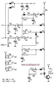
The circuit utilizes a relay or a transistor switch to control the power supply to the headlights based on the ignition status. When the ignition is turned on, the circuit allows current to flow to the headlights, enabling them to operate normally. Once the ignition is turned off, the relay or transistor is triggered to interrupt the power supply to the headlights, effectively turning them off.
The schematic typically includes an ignition switch, a relay or transistor, and the headlight circuit. The ignition switch is connected to the control terminal of the relay or the base of the transistor. When the ignition is active, the relay is energized, closing the circuit and allowing current to flow to the headlights. Upon turning off the ignition, the relay de-energizes or the transistor turns off, cutting off the power to the headlights.
To ensure reliability, additional components such as diodes may be included to prevent back EMF from damaging the control circuitry. A capacitor can also be integrated to provide a delay if desired, allowing for a brief period during which the headlights remain on after ignition off, enhancing visibility when exiting the vehicle.
This circuit is essential in automotive applications to enhance user convenience and prevent battery drain, thereby improving the overall efficiency and reliability of the vehicle’s electrical system.First, to indicate that the head lights (or the side lights) should be switched off after switching off the ignition contact. With this circuit, there should be no dead battery due to headlights that were left on. 🔗 External reference
Related Circuits
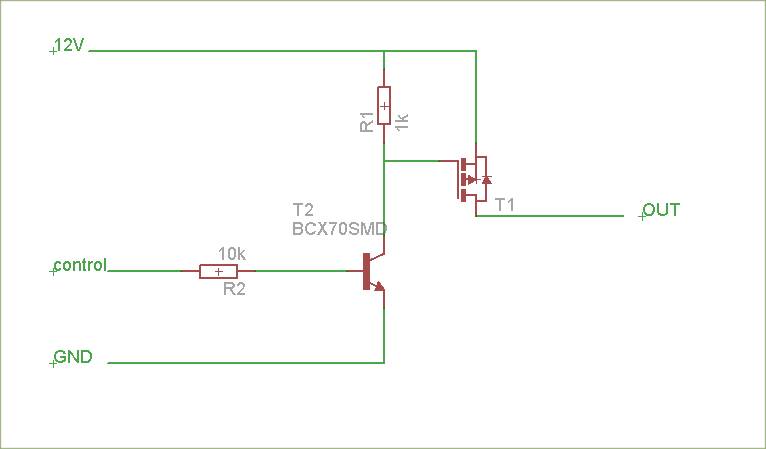
The schematic is attached. Suggestions for improvements are requested, particularly for adding reverse polarity connection protection. The logic level inputs (5 V) are designed to control two output voltages (12 V) using P-channel MOSFETs. The P-channel MOSFETs are ON...
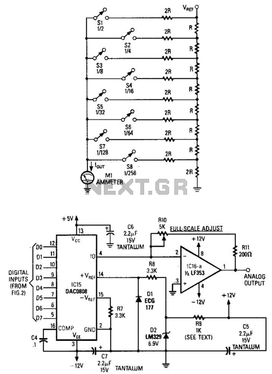
Figure A illustrates an R/2R resistor ladder. Each closed switch increases the current flow. A basic channel A/D converter is depicted in Figure B. The voltage reference (D2) is shared across all channels, although the value of the dropping...

This is a water sensor circuit design based on a Conductive Liquid Level Sensor. This single-chip circuit is compact and simple. It is an AC-excited fluid level sensor, which uses alternating current to provide biasing for the sensor probe,...
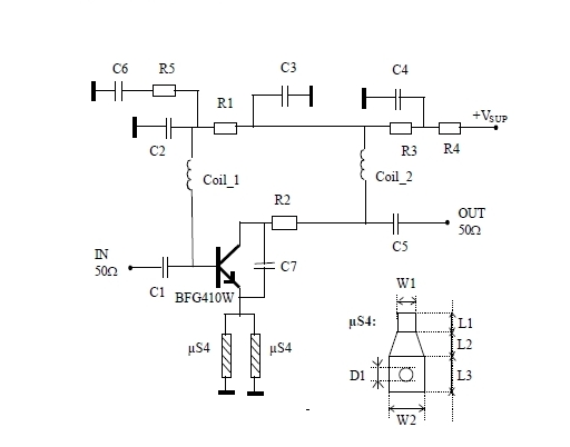
This 900 MHz amplifier circuit is constructed using the BFG480W transistor, which exhibits excellent linearity performance. As a result, the BFG480W is highly suitable for low-noise amplifiers (LNAs) that require high linearity. The 900 MHz amplifier circuit utilizing the BFG480W...
This circuit is a low-frequency Wien bridge sinusoidal oscillator designed for the audio range, characterized by very low distortion, making it suitable for testing various audio equipment. The circuit has undergone thorough testing, and a printed circuit board (PCB)...
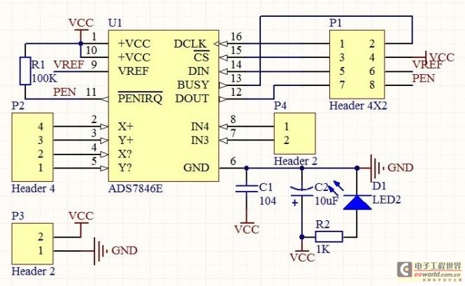
The touch control screen is a common feature in modern electronic products, typically incorporating a colored liquid crystal display (LCD) with a touch-sensitive interface. This technology is user-friendly and effectively replaces traditional fixed keypads. This document introduces the driving...
Warning: include(partials/cookie-banner.php): Failed to open stream: Permission denied in /var/www/html/nextgr/view-circuit.php on line 713
Warning: include(): Failed opening 'partials/cookie-banner.php' for inclusion (include_path='.:/usr/share/php') in /var/www/html/nextgr/view-circuit.php on line 713