
Whistle Responder Schematic
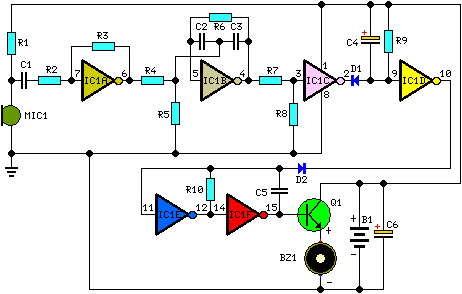
The circuit design employs a hex-inverter CMOS IC, specifically the CD40106 or similar, which integrates multiple functions into a single package, thus enhancing the compactness of the overall assembly. The electret microphone, chosen for its sensitivity and low power consumption, captures the sound of a whistle and converts it into an electrical signal. The signal is first amplified by IC1A, which increases its strength to a level suitable for further processing. IC1B, configured as a band-pass filter, utilizes passive components such as resistors and capacitors to create a filter circuit that allows only the frequency of interest (approximately 1.8 kHz) to pass through, effectively rejecting unwanted noise.
The output from the band-pass filter is then fed into IC1C, where the Schmitt trigger action ensures that the signal is cleanly squared, providing a digital output that is less susceptible to noise. This digital signal triggers IC1D, which is designed as a monostable multivibrator. Upon receiving the trigger from IC1C, IC1D generates a high output for a fixed duration of two seconds, after which it returns to a low state.
The output from IC1D is utilized to initiate the astable multivibrator configuration formed by IC1E and IC1F. This configuration generates a square wave output at a frequency of 3 to 5 Hz, which is then used to drive a transistor (Q1). The transistor acts as a switch, controlling the current flow to the piezo buzzer (BZ1), which produces the audible beeping sound. The intermittent nature of the beeping is achieved through the oscillation of the multivibrator, providing a simple yet effective solution for the intended application.
Overall, this circuit exemplifies an efficient design that leverages common electronic components to create a functional device with practical uses, particularly in personal item tracking or alert systems.Some 20 years ago it was common to see small key-holders emitting an intermittent beep for a couple of seconds after its owner whistled. These devices contained a special purpose IC and therefore were not suited to home construction. The present circuit is designed around a general purpose hex-inverter CMos IC and, using miniature components and b
utton clock-type batteries can be enclosed in a matchbox. It is primarily a gadget, but everyone will be able to find suitable applications. This device beeps intermittently for about two seconds when a person in a range of around 10 meters emits a whistle. The first two inverters contained in IC1 are used as audio amplifiers. IC1A amplifies consistently the signal picked-up by the small electret-microphone and IC1B acts as a band-pass filter, its frequency being centered at about 1.
8KHz. The filter is required in order to select a specific frequency, the whistle`s one, stopping other frequencies that would cause undesired beeper operation. IC1C is wired as a Schmitt trigger, squaring the incoming audio signal. IC1D is a 2 second-delay monostable driving the astable formed by IC1E & IC1F. This oscillator generates a 3 to 5Hz square wave feeding Q1 and BZ1, thus providing intermittent beeper operation.
🔗 External reference
Related Circuits
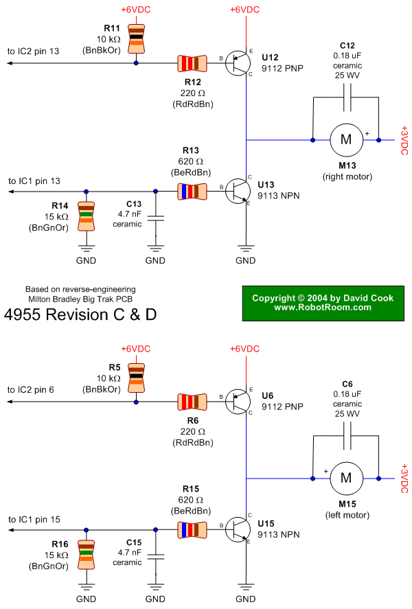
Schematic of Big Trak's motor driver circuit. The toy includes 9112 and 9113 transistors (and sometimes 2N6715) because the 75494 chip cannot supply enough current to run the Big Trak's motors by itself. The motor driver circuit for the Big...
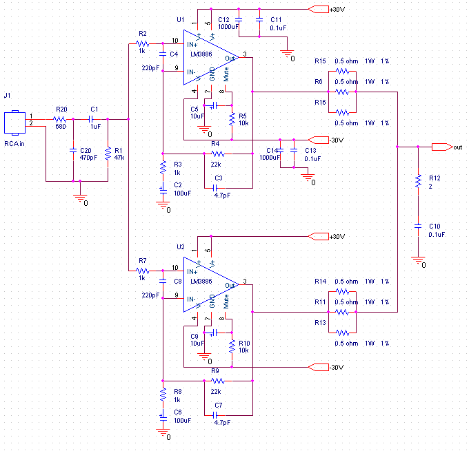
This audio amplifier design utilizes two LM3886 chips per channel in a parallel configuration, based on the PA100 parallel amplifier detailed in National Semiconductor's application note AN1192. The amplifier can deliver approximately 50W into an 8-ohm speaker and 100W...
The series consists of input buffers that match the output. This configuration resembles a common collector circuit with a reinforcement factor of 1. A resistor value is included to limit the current usage. The effectiveness of this circuit largely...
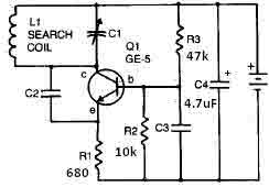
This metal detector circuit requires a power supply of 9 volts (DC) or a 9-volt battery. The circuit includes a variable capacitor C1 valued at 365 pF, a 100 pF silver mica capacitor C2, a 0.05 µF disc capacitor...
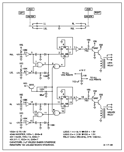
Advanced power door lock management is essential in modern automotive systems. The need to reduce vehicle weight has led to the requirement for a schematic of the driver's door lock mechanism for a 1993 Chevy G-20. The third wire...
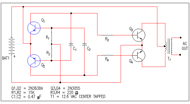
A small bias on the bases of Q1 and Q2 through R1 and R2 assists in initiating the circuit. This provides each transistor's base with a slight forward bias, enabling both transistors to conduct when the circuit is initially...