
Motorcycle anti-theft Alarm

The circuit described is designed to enhance the security of a motorcycle by integrating an intermittent siren output and an automatic reset feature. The system can be activated in two primary ways: manually via a key-switch or hidden switch, or automatically when the ignition is turned off. This dual functionality allows for flexibility in operation, catering to various user preferences and scenarios.
The siren output is intended for use with an electronic siren that operates within a current range of 300 to 400 mA. Utilizing the motorcycle's existing horn is discouraged due to its accessibility and potential for disconnection by an intruder. If the horn is preferred, it is crucial to implement a relay that can handle the higher current requirements, as the alarm relay itself is not rated for such loads.
To facilitate additional functionalities such as immobilization of the bike or activating the lights, external relays can be incorporated into the circuit. This modular approach allows for customization based on the user’s security needs.
The circuit design supports the inclusion of multiple normally-open switches, which can be strategically placed to enhance security. For instance, tilt switches can be employed to trigger the alarm when the motorcycle is moved from its upright position, such as when it is lifted off the side-stand or pushed off the center-stand. Additionally, micro-switches can be utilized to secure removable panels, further fortifying the motorcycle against unauthorized access.
In summary, this circuit provides a robust solution for motorcycle security, combining manual and automatic activation methods, a dedicated siren output, and the capacity for integration with various external components to enhance functionality and protection.This circuit features an intermittent siren output and automatic reset. It can be operated manually using a key-switch or a hidden switch; but it can also be wired to set itself automatically when you turn-off the ignition. By adding external relays you can immobilize the bike, flash the lights etc. The circuit is designed to use an electronic Siren drawing 300 to 400mA. It`s not usually a good idea to use the bike`s own Horn because it can be easily located and disconnected.
However, if you choose to use the Horn, remember that the alarm relay is too small to carry the necessary current. Connect the coil of a suitably rated relay to the "Siren" output. This can then be used to sound the Horn, flash the lights etc. Any number of normally-open switches may be used. Fit "tilt" switches that close when the steering is moved or when the bike is lifted off its side-stand or pushed forward off its centre-stand. Use micro-switches to protect removable panels and 🔗 External reference
Related Circuits

When the light beam that falls on the CDS photocell is interrupted, the transistor (EN3904) conducts, triggering SCR1 (CI06) and activating the alarm bell. SI resets the SCR. The alarm bell should be a self-interrupting electromechanical type. The lamp...

A low-frequency oscillator (Q1) modulates a high-frequency oscillator (Q2) along with its associated timing capacitor. The output frequency varies continuously. The circuit comprises two primary components: the low-frequency oscillator (Q1) and the high-frequency oscillator (Q2). The low-frequency oscillator is responsible...

When the AC mains supply fails, this circuit triggers an alarm to alert the user. Additionally, it offers a backup light to assist in locating a flashlight or other emergency lighting. This circuit is designed to provide immediate notification and...
The circuit utilizes the functions of reed switches to create a gate alarm powered by a universal AC/DC power supply oscillator. The circuit operates by integrating reed switches, which are sensitive to magnetic fields, into an alarm system designed to...
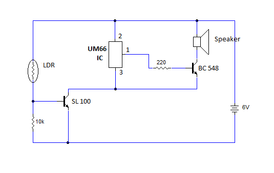
This article provides instructions for creating a light-sensitive morning alarm circuit. The circuit utilizes an LDR (Light Dependent Resistor) or photoresistor to detect morning light, which triggers the alarm section. When light is detected, the circuit produces a melodious...

When a printer is shut down, an alarm is triggered. The input can be either a high-to-low or low-to-high transition. This corresponds to the logic level indicating whether the printer is on or off. The oscillator generates an interrupted...
Warning: include(partials/cookie-banner.php): Failed to open stream: Permission denied in /var/www/html/nextgr/view-circuit.php on line 713
Warning: include(): Failed opening 'partials/cookie-banner.php' for inclusion (include_path='.:/usr/share/php') in /var/www/html/nextgr/view-circuit.php on line 713