
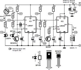
Mains Supply Failure Alarm
This circuit is designed to provide immediate notification and assistance during a power outage. It typically consists of several key components: a power supply, an alarm system, a backup light source, and a control unit.
The power supply is often derived from a rechargeable battery, which ensures that the circuit remains operational even when the mains power is unavailable. The control unit monitors the status of the AC mains supply using a relay or a microcontroller. When a power failure is detected, the control unit activates the alarm system, which may include a buzzer or speaker to emit a loud sound, alerting individuals in the vicinity of the outage.
Simultaneously, the control unit activates the backup light source, which can be an LED or incandescent bulb, providing illumination to assist users in navigating their environment safely. The backup light may be designed to remain lit for a predetermined duration or until the mains power is restored, depending on the circuit's configuration.
Additional features may include a test button to verify the functionality of the alarm and light, as well as indicators to show the status of the battery charge. The circuit may also incorporate a low battery indicator to alert users when the backup power source requires recharging.
Overall, this circuit serves a critical role in enhancing safety and convenience during power outages, ensuring that individuals can quickly and effectively respond to unexpected loss of electrical power.Whenever AC mains supply fails, this circuit alerts you by sounding an alarm. It also provides a backup light to help you find your way to the torch or th.. 🔗 External reference
Related Circuits
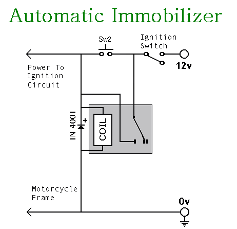
This circuit includes an intermittent siren output with automatic reset functionality. It can be activated manually via a key switch or a concealed switch, or it can be configured to activate automatically when the ignition is turned off. By...
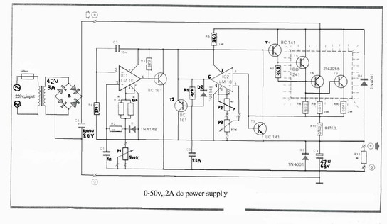
A variable power supply designed for laboratory use. It utilizes two integrated circuits (ICs) to provide adjustable output voltage and current. This variable power supply is engineered to meet the diverse needs of laboratory applications, offering flexibility in output voltage...
Additionally, it may be necessary to include another input capacitor to mitigate high-frequency noise, although this is not directly related to the main question. The objectives are to achieve a voltage output of 0 - 12 V with a...

The BE-150 mainframe computer features a switching power supply circuit. The circuit utilizes the oscillation control IC TIA94. A 22V voltage is supplied through the power switch S1, fuse, filter capacitor C21, L2, and a mutual inductance filter, which...
This circuit can be constructed using readily available low-cost components, some of which may be found in a junkbox. The specified value of 22 ohms for resistor R1 results in an average current of approximately 65 mA through the...
A mixer has been purchased without a power supply unit (PSU). The user does not require the 48V phantom power and is inquiring if an 18V DC wall adapter can be used instead. Additionally, the user seeks information on...