
panasonic wv f15 camera
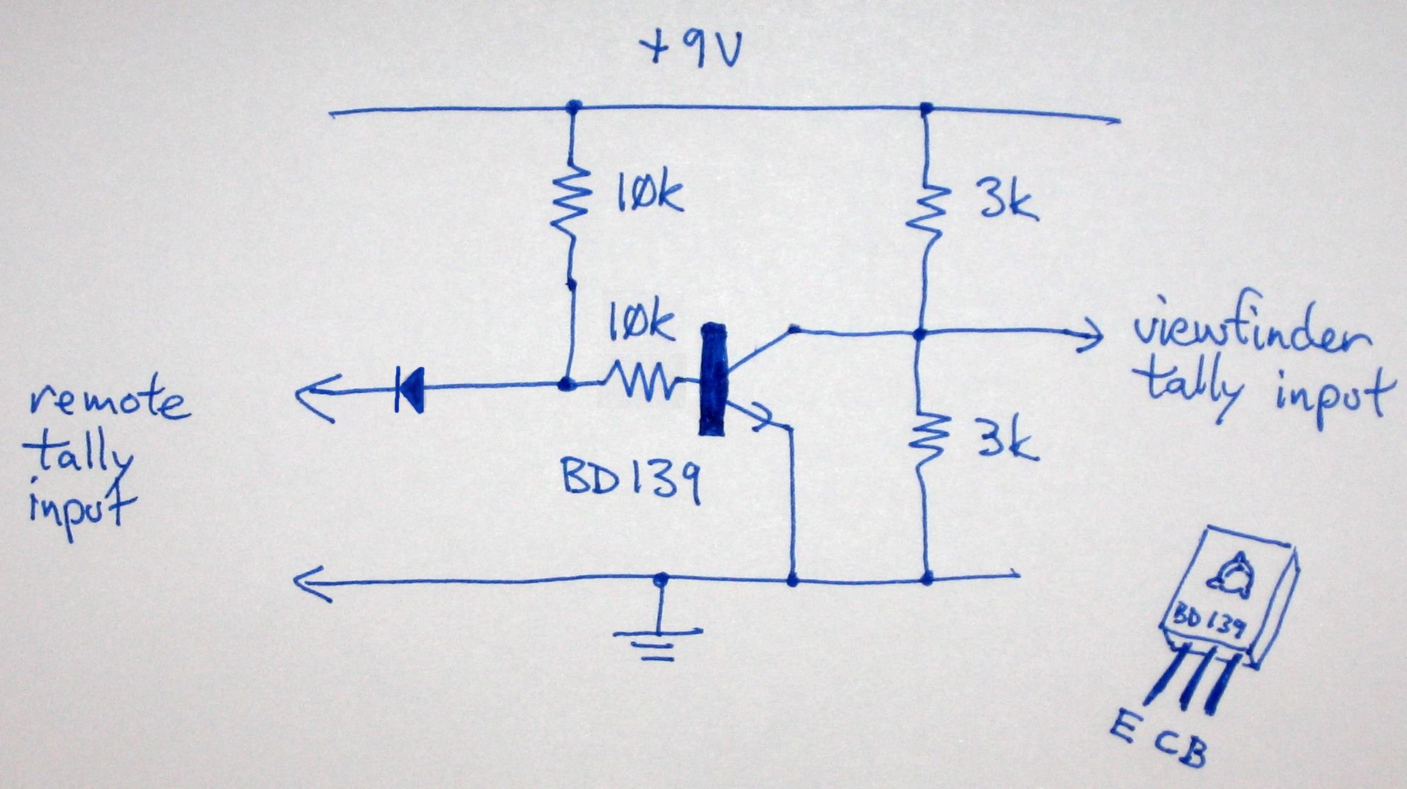
To activate the tally light on an F15 camera viewfinder in the absence of a Camera Control Unit (CCU) or Remote Control Unit (RCU), a direct wiring approach can be employed. The tally light serves as a visual indicator to inform the operator when the camera is actively recording or transmitting.
To implement this solution, first identify the pin configuration of the viewfinder's connector. The tally light typically requires a power source and a signal input to function correctly. A common method involves connecting the tally light directly to the camera's power supply, ensuring that the voltage levels are compatible with the light's specifications.
Next, the signal input for the tally light can be derived from the camera's recording status. This can be achieved by tapping into the camera's internal circuitry, specifically the output that indicates when the camera is in record mode. It is crucial to isolate this signal to prevent any interference with the camera's normal operation.
When wiring the tally light, use appropriate gauge wires to handle the current without overheating. Additionally, ensure all connections are secure and insulated to prevent short circuits. Testing the setup before finalizing the installation is advisable to confirm that the tally light operates as intended.
In summary, while the absence of a CCU or RCU complicates the activation of the tally light on an F15 camera viewfinder, a direct wiring solution can be implemented by connecting the tally light to the camera's power supply and recording status output. Proper attention to electrical specifications and safety precautions is essential for successful operation.How to make the tally light work on the F15 camera viewfinder when you don`t have the CCU/RCU.. 🔗 External reference
Related Circuits
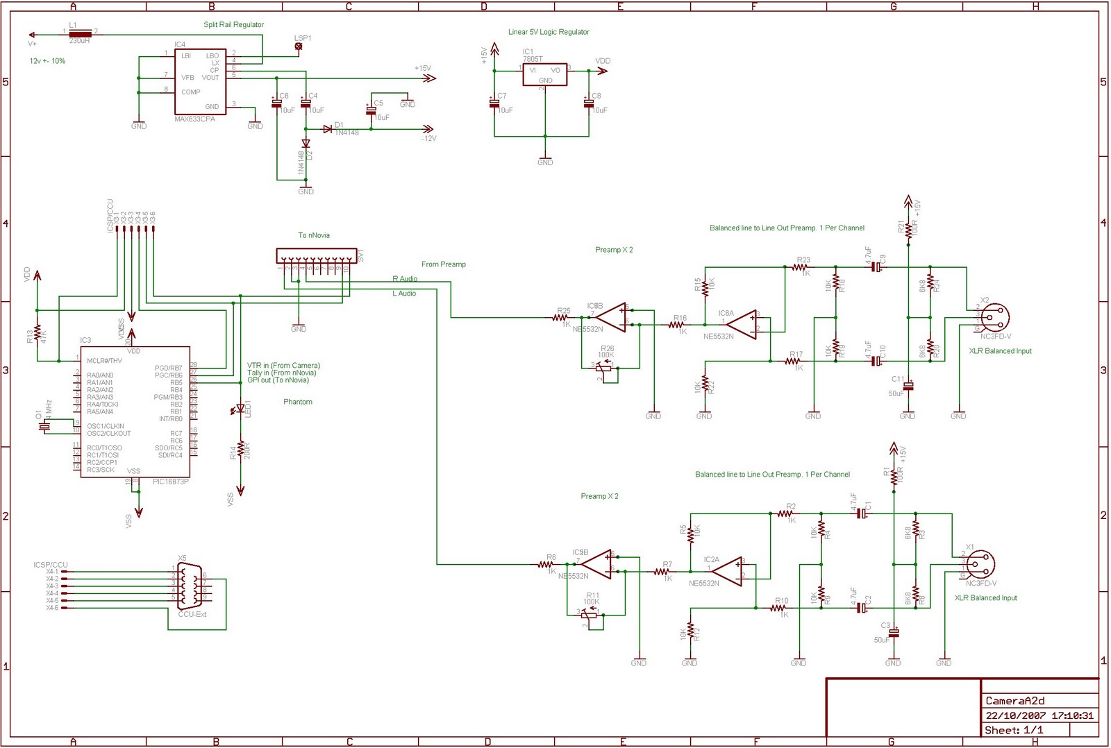
This is an ongoing project focused on creating a circuit to interface the nNovia QC120 A2D2 recorder with a Sony DXC-325P camera equipped with a CA-325P studio back. The final design is still in progress. A circuit based on...

The camera has been wired with external shutter leads, and a method is needed to trigger them. These leads must be connected together via a relay at regular intervals, approximately every 2 seconds, starting from launch. A 555 timer...
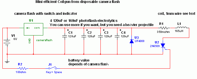
This project is a fun and safe activity for individuals interested in magnetically launching projectiles. The operation involves placing a ferromagnetic projectile at one end of a coil and applying a power pulse. The key is to turn off...
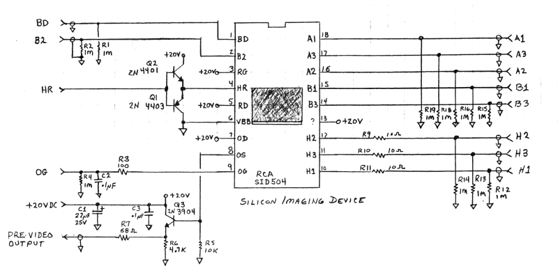
RCA developed some of the first commercially available CCD (Charge-Coupled Device) chips. A CCD is a silicon-based solid-state imaging device that replaces the older vidicon tubes. CCDs consist of a two-dimensional array of photodetectors linked to an array of...
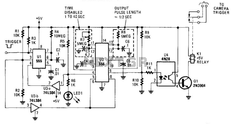
This circuit is designed to activate a camera shutter. Grounding pin 2 of U1 causes pin 4 of U1 to go high, which triggers both timers of the dual timer U1. One output maintains the reset (pin 4) of...
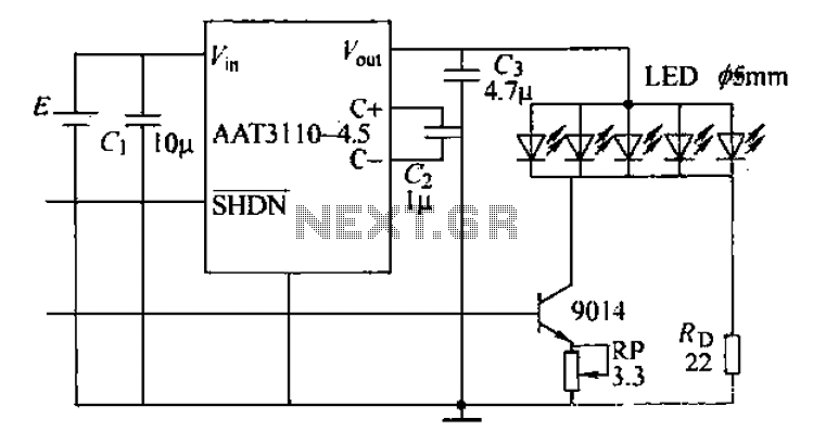
A circuit designed for a phone photo camera flash that delivers a peak current of 200mA. It utilizes the AAT3110-4.5 capacitive charge pump chip to boost and regulate the lithium battery voltage to 4.5V. This voltage powers a series...