
Motorized Remote control with ATMEGA328
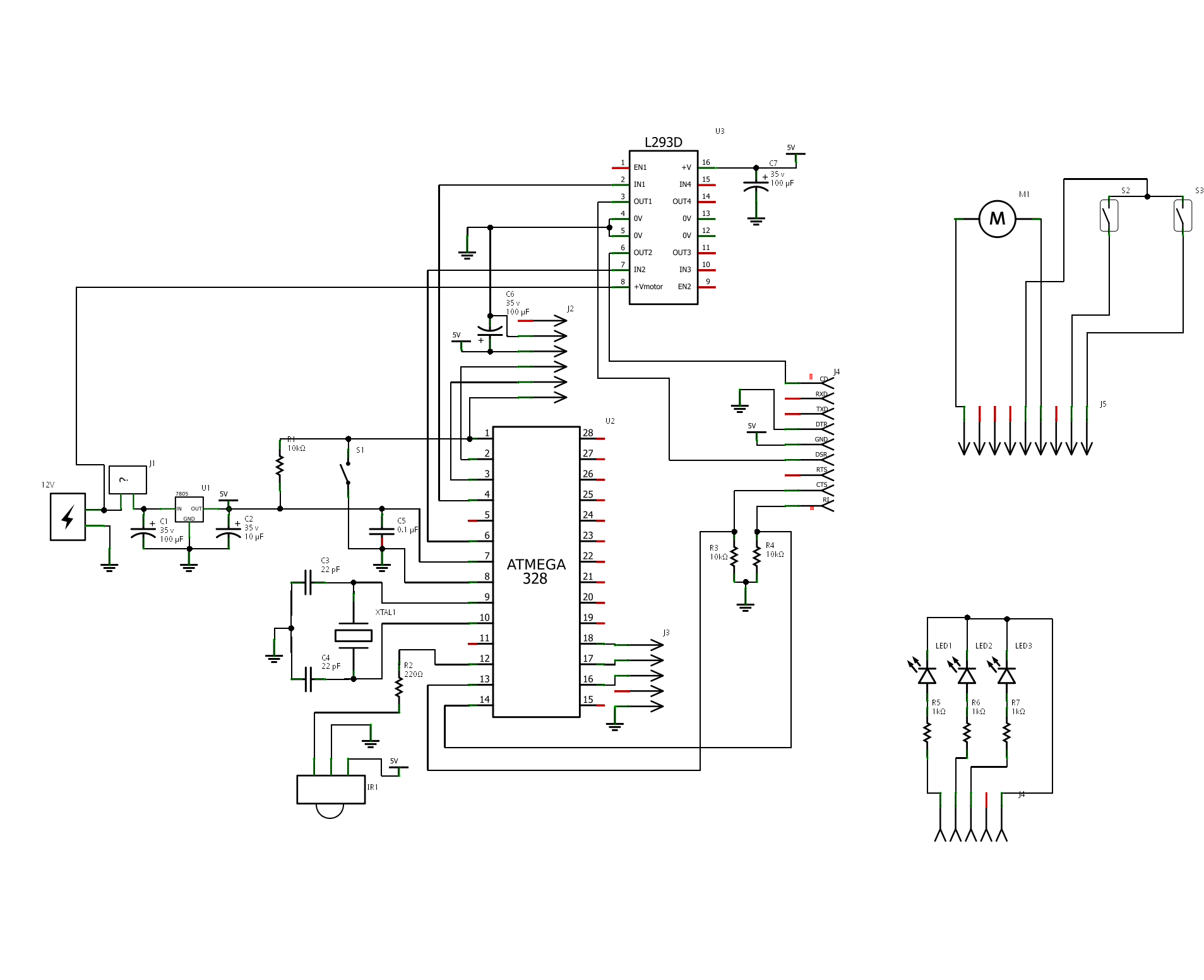
The "Motorized Curtain" project utilizes an ATmega328 microcontroller, which serves as the central processing unit for controlling the curtain's movement. The microcontroller is programmed with the Arduino bootloader, allowing for easy programming and integration with Arduino IDE.
The motor driver employed is the L293B, which is a dual H-bridge driver capable of controlling the direction and speed of the DC motor sourced from an old printer. External diodes are added to the L293B to protect against back EMF generated by the motor, which is a common requirement when driving inductive loads.
The control mechanism is facilitated by an IR receiver, specifically the TSOP 1738, which is designed to receive signals from an IR remote control, in this case, a remote from a PixelView TV Tuner. The remote sends commands to the microcontroller, enabling the user to control the curtain's movement. The software developed for this project allows for the curtain to be moved smoothly from left to right and back, as well as in incremental steps.
To provide feedback on the position of the curtain, a small magnet is affixed to the last peg of the curtain rail. This magnet interacts with two reed contacts positioned at either end of the rail. When the magnet passes by a reed contact, it closes the circuit, signaling the microcontroller to stop the motor, thereby preventing over-travel of the curtain.
The last peg is mechanically linked to the DC motor via a cord, which also connects to a reel. This setup allows for effective movement of the curtain along the rail. The source code for the microcontroller is written in Arduino programming language, leveraging the NECIRRcv library for decoding the signals received from the IR remote control, thus enabling precise control over the curtain's operation.The project is "Motorized Curtain" with Remote control. It is made up of MCU ATMEGA328 with Arduino BootLoader, motor driver L293D ( i used L293B with external diodes, because i couldn't find L293D ), IR Receiver TSOP 1738, DC Motor from an old printer and other small parts. To control it, i use IR remote control from a PixelView TV Tuner. The software allows moving the curtain from left to right and back, or on steps. On the last peg (of the curtain rail) is attached a small magnet, which interacts with the two reed contacts, placed on the two ends of the rail. The last peg is moved by a cord, which connects it to the motor on one side and a reel to the other. Source Code is written on Arduino. I use NECIRRcv Libraries for decode code from IR Remote Control. 🔗 External reference
Related Circuits
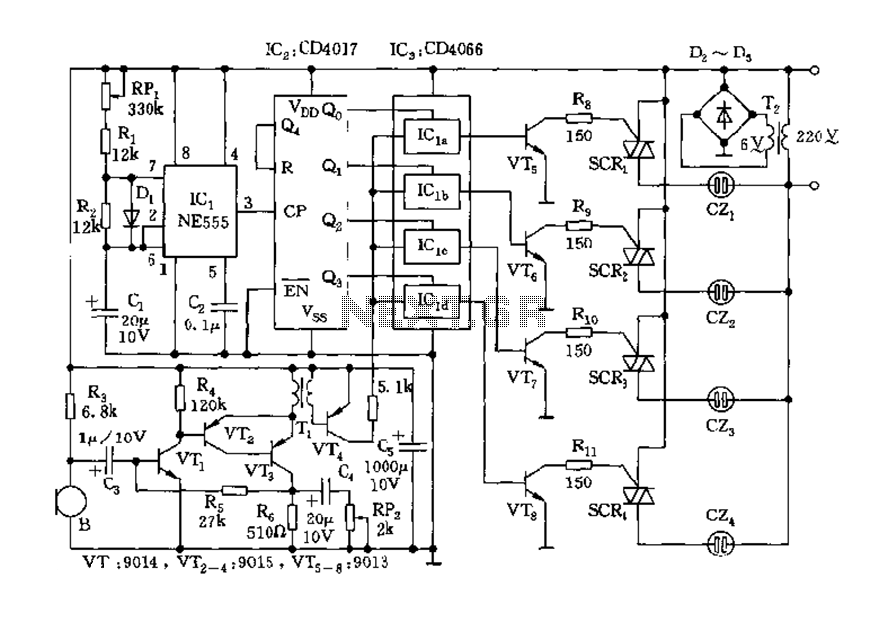
The circuit includes a controller that integrates an acoustic-electric conversion and amplification circuit, a clock pulse generator, a counting circuit, and a control circuit. It manages four accompanying music tracks and flashing lights. Microphones (MIC) convert sound into electrical...
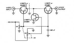
A variable gain amplifier controlled by voltage, functioning as a video amplifier. It utilizes three Field Effect Transistors (FETs) of type U1897E, which can be substituted with 2N4091. The described variable gain amplifier is designed to adjust its gain based...
The VNGBOX microcontroller must generate a precise, high-resolution, and low-noise DC control voltage to accurately steer the reference oscillator phase. Any noise on this signal can introduce noise to the reference, and any non-linearity, particularly unexpected steps in the...
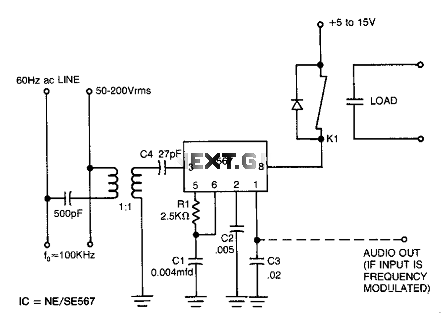
The following circuit illustrates a Radio Remote Control Circuit Diagram. This circuit is based on the UM91214B IC. Features include the use of DTMF (dual-tone multi-frequency) technology. The Radio Remote Control Circuit utilizes the UM91214B integrated circuit, which is specifically...
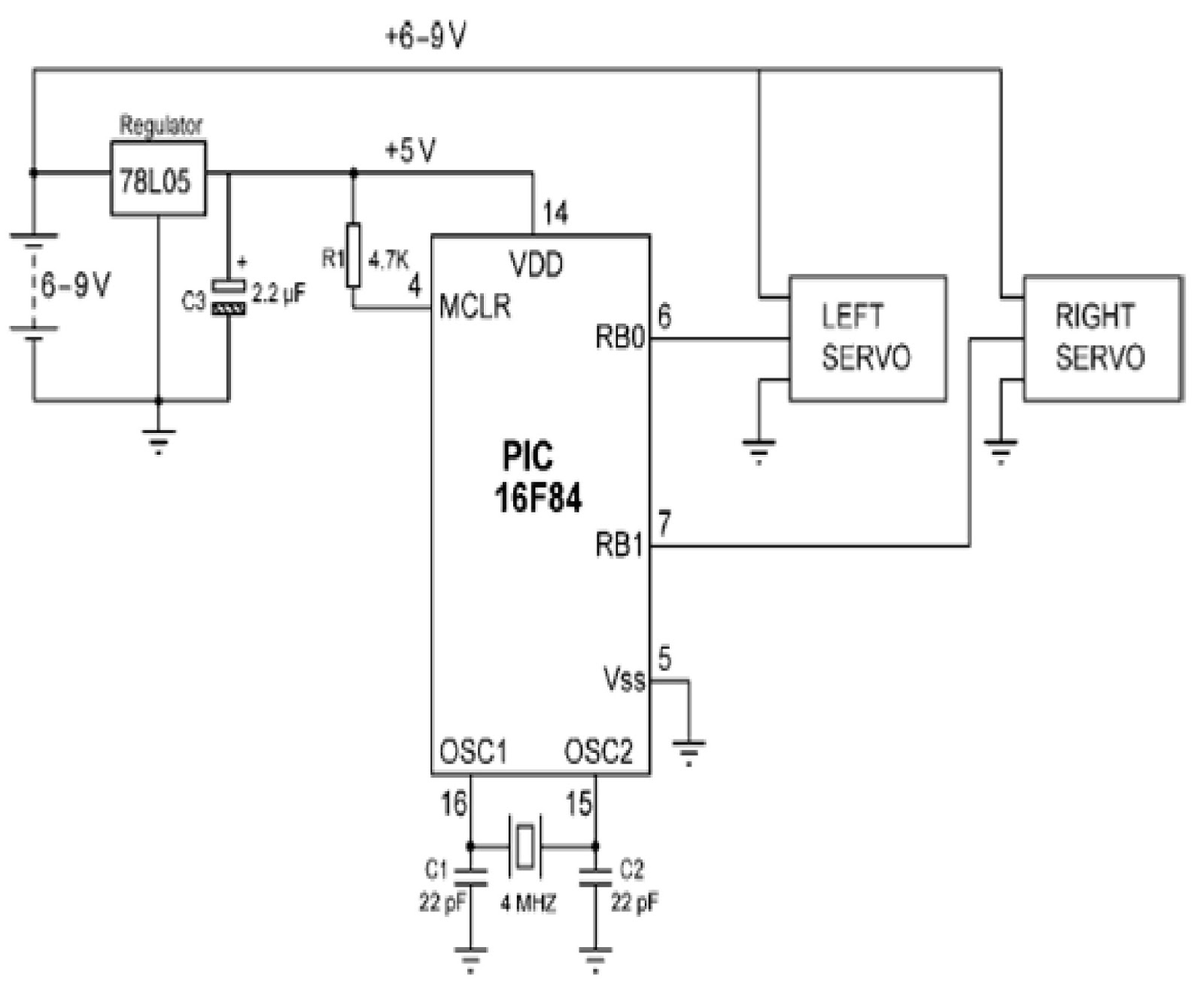
Mobile robots are utilized in various industrial, commercial, research, and hobby applications. This project focuses on controlling a mobile robot using servomotors. The robot is based on a well-known mobile robot called Boe Bot, developed by Parallax. The basic...
Carrier current remote control device or intercom circuit diagram as follows: The circuit diagram for a carrier current remote control device or intercom system typically involves the use of carrier current technology to transmit audio signals over existing electrical...