
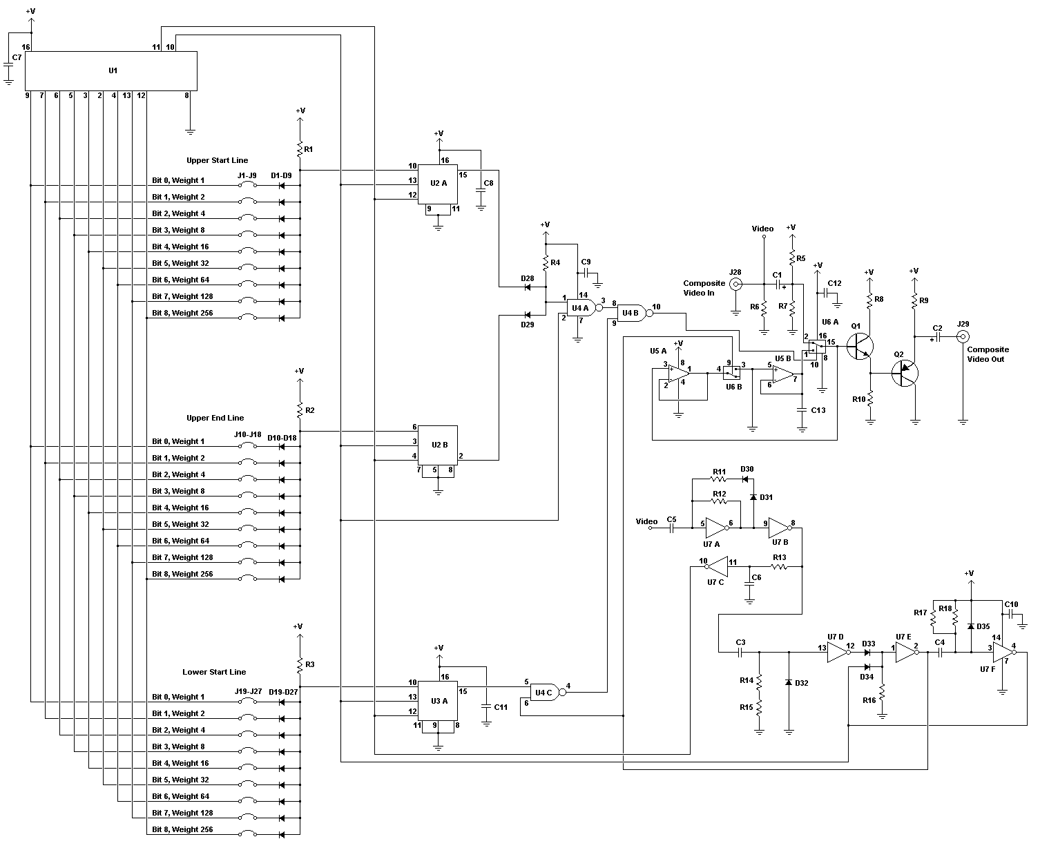
Motorized Video Camera Mount

The camera rotator circuit is designed to facilitate precise control of motor movements through the use of a 2716 EPROM, which effectively replaces multiple discrete logic gates with a compact and efficient solution. The EPROM stores a comprehensive logic table that dictates the operational behavior of the motor driver, specifically the H-bridge circuit. The H-bridge configuration is essential for enabling bidirectional motor control, allowing the motor to rotate in both clockwise and counterclockwise directions based on user input and sensor feedback.
In this circuit, the limit sensors play a critical role in ensuring that the motor does not exceed its physical boundaries. When the clockwise limit sensor is activated, the motor ceases to rotate in that direction, while the counterclockwise limit sensor performs the same function for counterclockwise rotation. The incorporation of four bits from these sensors and the direction control switch into the EPROM address lines allows for dynamic control of the motor's operation.
The use of buffered control switch signals via a 7400 quad NAND gate enhances the circuit's robustness, particularly when long control wiring is necessary. The choice of a shielded control wire, such as beldfoil, minimizes interference and ensures reliable signal transmission, with grounding at one end to prevent ground loops that could introduce noise into the system.
The H-bridge design, featuring both N-channel and P-channel MOSFETs, allows for efficient switching and control of the motor's direction. The diagonal activation of the transistors ensures that the motor can be driven forward or backward, while the system is designed to prevent simultaneous activation of conflicting transistor pairs, which could lead to circuit damage. The careful programming of the EPROM logic table is crucial for maintaining operational integrity and preventing undesirable output states that could cause overheating or failure of the components.
Overall, this camera rotator circuit exemplifies a well-engineered solution for motor control, leveraging the advantages of EPROM technology and H-bridge configurations to achieve reliable and efficient performance in applications requiring precise motor positioning.The camera rotator circuit uses a 2716 EPROM to store a table of logic values that control the motor driver (H-bridge) circuit. The EPROM data is shown in the schematic. By using the EPROM, a large number of discrete gates are eliminated. The logic table is designed to allow the motor to turn clockwise until the clockwise limit sensor is activated
. The same operation happens with counter clockwise rotation and the counter clockwise limit sensor. Four bits of input come from the limit sensors and the direction control switch, these go to the EPROM address lines. All of the input signals are low-active. Four EPROM outputs go to the four H-bridge transistor gates. The control switch signals are buffered through the 7400 quad NAND gate, this allows for a long control wire.
The control wire should be a shielded type such as beldfoil and the shield should be grounded at only one side. The H-bridge array consists of two N-channel MOSFETs and two P-channel MOSFETs. Diagonal pairs of transistors are turned on to move the motor one way or the other. If all of the transistors are off, the motor does not move. Note that the P channel transistors turn on with a 0 logic output level and the N channel transistors turn on with a 1 logic output level.
There are several disallowed output states, if the wrong two transistors are turned on, the transistors and voltage regulator would heat up and possibly be destroyed. Don`t do this. If the EPROM is programmed correctly, this should never happen. 🔗 External reference
Related Circuits
Have you ever attempted to copy a commercially produced video only to end up with a distorted and jumpy image? If so, then you have run afoul of MacroVision. MacroVision is the most popular copy protection scheme used on...
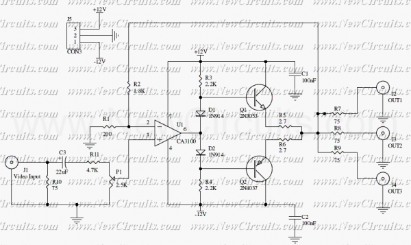
This circuit is useful to amplify and distribute video signals with low noise and without losses. The CA3100 is a fast opamp designed to amplify video signals. Set the P1 to control the input signal level to have a...
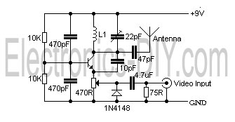
This is a simple video transmitter capable of transmitting signals up to 50 meters. It can be utilized with cameras or other video sources and allows viewing on VHF channel analog televisions. The video transmitter operates on a supply...
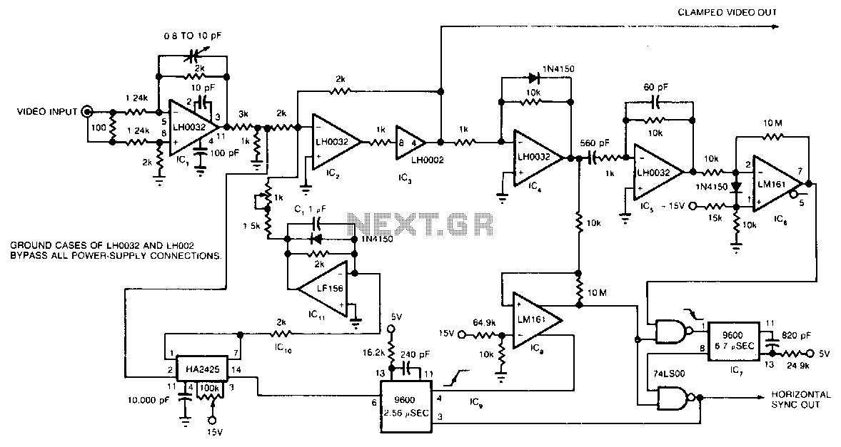
The circuit utilizes a track-and-hold amplifier in a closed-loop configuration to clamp the back-porch voltage of a standard video waveform to 0 V. The outputs of the circuit include a clamped composite video signal and a TTL-level horizontal blanking...
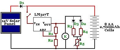
The circuit is designed to power a CCTV camera, provide lighting inside a nestbox, and charge batteries using a photovoltaic (PV) solar panel. It includes a circuit diagram for a solar-powered wireless CCTV camera with battery backup. D1 is...
This circuit enables wireless audio and visual transmission to a television, which serves as a receiver, thus negating the need for a separate monitor. Additionally, it can be connected to a VCR or CCD camera, facilitating the establishment of...