
Motorola DSP Receiver

This project originated in 1994 when Ralph Stirling, KC3F, and another engineer followed Rick Campbell, KK7B's, recommendations from his initial article on the R2 receiver. They utilized Rick's R2 receiver alongside the Texas Instruments C5X DSK to create a DSP-based direct conversion receiver. The DSK was enhanced with a custom daughterboard containing an additional TLC32040 codec. The DSP replaced the analog phase shift network with its digital equivalent and a sharp digital filter, achieving nearly 50 dB of opposite sideband rejection. However, the system required further adjustments to the gain distribution before it was viable for practical use. Around this time, Motorola released the DSP56002EVM evaluation board, rendering the previous TI board implementation obsolete. The integrated 16-bit stereo codec from Crystal Semiconductor on the Motorola board significantly outperformed the two TI 12-bit TLC32040 codecs. Moreover, the Motorola 56002 processor operated with 24 bits of precision, compared to the 16 bits of the TI TMS320C5X, indicating a clear need for a redesign.
The redesign process began during the winter quarter of 1996 when the instructor assigned students to test the Motorola EVM as a replacement for the TI DSK. The results demonstrated that modifying a filter program provided by Motorola for basic SSB demodulation was straightforward and yielded superior performance compared to the TI-based receiver. Extensive improvements were made to the design over the summer. The article outlines this enhanced system, which utilizes the R2 receiver due to its high dynamic range and accessibility. The image-reject down-converter incorporated in the design generates in-phase (I) and quadrature (Q) channels, supplying all necessary signals for demodulating various modulation types, resulting in a band-pass signal. The in-phase modulation is denoted as x(t), while the quadrature modulation is represented as y(t). The demodulators discussed in this article support AM, DSB, CW, ISB, and SSB modes. Future software updates will enable the addition of further modulation modes.Ralph Stirling, KC3F, and I built the first generation using a Texas Instruments C5X DSK digital signal processing starter kit. Let it suffice to say that the second generation is a tremendous improvement over the first, because it uses a much more suitable DSP evaluation board from Motorola, the DSP56002EVM.
You may wonder what the big deal is. Why are so many of the latest radios coming with DSP demodulators and filters Digital techniques have several advantages. Probably the most exciting is that everything is done in software. That means when I design a new demodulator you can download it to your radio and then you have my new demodulator. No soldering; no hunting parts; no ugly modifications; it`s so easy! Another benefit is that results are predictable. Component tolerances are not a factor as they are with analog signal processing. Simulations are easier to do and their results more closely approximate what happens in the actual system.
Yet another advantage results from the speed of today`s DSPs. Nowadays it is quite realistic to have a digital filter with the equivalent of hundreds of poles, a filter that would require hundreds of inductors, capacitors or crystals in the analog world. Few analog designers use more than ten poles in a filter, because it`s very difficult to make designs with more work properly.
This project actually started back in 1994. Ralph Stirling, KC3F, and I did exactly what Rick Campbell, KK7B, suggested in his original article on the R2 receiver. We used Rick`s R2 receiver and the Texas Instruments C5X DSK digital signal processing starter kit to construct a DSP based direct conversion receiver.
We modified the DSK with our custom daughter board containing another TLC32040 codec. The DSP replaced the analog phase shift network with its digital counterpart and a sharp digital filter. We were able to obtain almost 50 db of opposite sideband rejection. However, it wasn`t quite ready to take home and tune to 20 meters. The gain distribution needed adjustment. About the time we got this far, Motorola came out with their DSP56002EVM evaluation board. It made what we did with the TI board obsolete. The Crystal Semiconductor 16 bit stereo codec built into the Motorola board was much better than the two TI 12 bit TLC32040 codecs.
The Motorola 56002 processor used 24 bits of precision and the TI TMS320C5X used only 16. It was obvious that we needed to start over. That start didn`t come until I taught Communications Systems during winter quarter of 1996. As a homework assignment I had my students try the Motorola EVM in place of the TI DSK. It proved simple to modify a filter program supplied by Motorola to do the basic filtering necessary for SSB demodulation, and it worked much better than the TI based receiver had. I spent many hours during the summer improving on that design. This article describes that improved system. We chose the R2 receiver not only because of its high dynamic range and ready availability, but also for the image-reject down-converter it uses.
Its in-phase (I) and quadrature (Q) channels provide all the signals needed to demodulate any type of modulation resulting in a band-pass signal. These two signals are called the in-phase modulation, x(t), and the quadrature modulation, y(t). See the block diagram of the receiver in Figure (Generalized Receiver). The demodulators described in this article are for AM, DSB, CW, ISB and SSB, but because other modes need only new software we can expect more modes to be available in t
🔗 External reference
Related Circuits
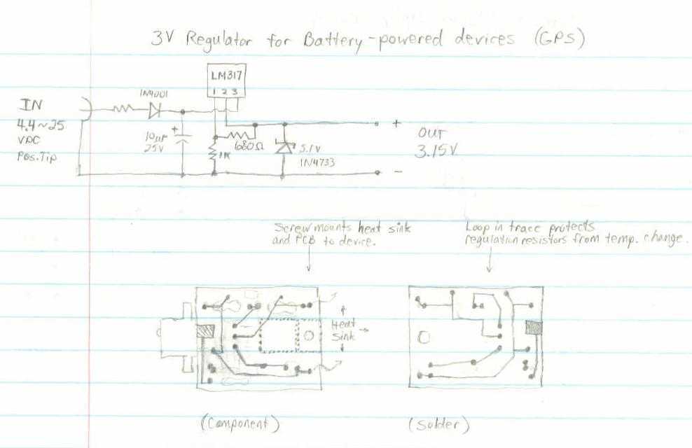
This GPS receiver is powered by 2 AA batteries. They are only strong enough for the GPS to stay on for about two hours, and this seems like quite a waste. I would like to be able to use...
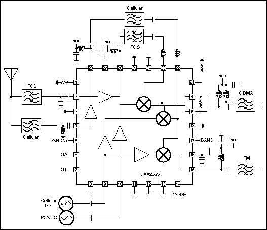
This technical note focuses on determining the system specifications of a CDMA receiver to establish practical specifications for a low noise amplifier and down converter. The design of a CDMA (Code Division Multiple Access) receiver necessitates a comprehensive understanding of...
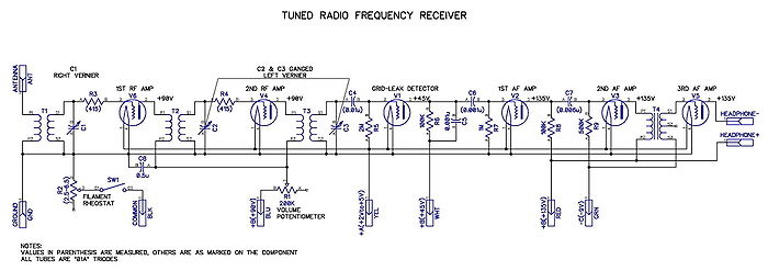
A tuned radio frequency (TRF) receiver is a radio receiver typically consisting of multiple tuned radio frequency amplifiers followed by circuits for detecting and amplifying the audio signal. A three-stage TRF receiver includes an RF stage, a detector stage,...
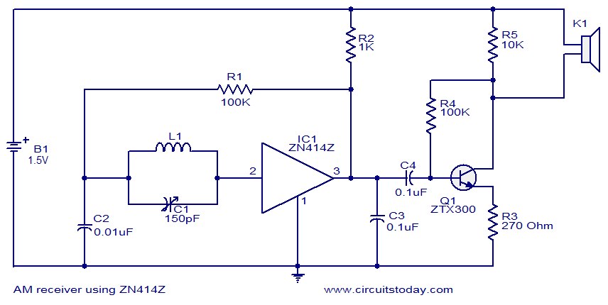
This circuit diagram represents a simple single-chip AM radio, designed around the ZN414Z integrated circuit (IC), which is a ten-transistor tuned radio frequency receiver. The IC features three leads and is housed in a TO92 package. It incorporates all...
Superheterodyne receivers have been mass-produced since around 1924, but for reasons of cost did not become successful until the 1930s. Superheterodyne receivers represent a pivotal advancement in radio technology, characterized by their ability to convert high-frequency signals into lower...
The tuning stage of this long-wave and medium-wave radio receiver also functions as an active antenna, which can be optimally positioned for the best reception. The circuit is completely independent from the receiver, which includes a demodulator that provides...