
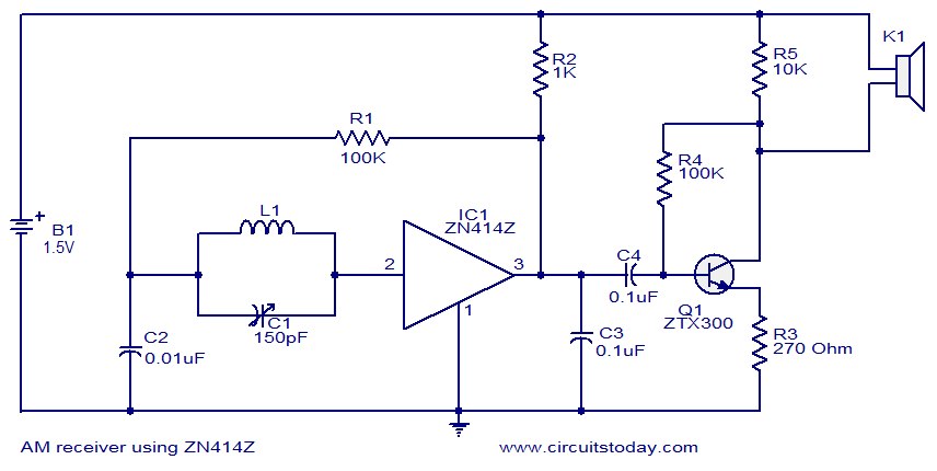
AM receiver using ZN414
To replace the speaker used in a typical AM receiver circuit with a relay for alternative applications, it is essential to ensure that the relay can handle the output from the circuit. The relay should be connected in place of the headphones, allowing it to be activated by the audio signal from the IC. Proper selection of the relay is crucial, as it must be compatible with the output characteristics of the circuit.
For sourcing the ZN414Z IC in Colombia, it is advisable to search online for electronics distributors or local suppliers. Searching for ZN414 radio, MK484, or TA7642 ICs can yield results for purchasing options. Reliable sources, such as eBay, may provide the TA7642 at a competitive price.
The receiver is designed to cover AM/Medium Wave and LW Long Wave frequencies. Some users may experiment with short waves, particularly in the 49-meter band, although the IC operates effectively up to a maximum frequency of 3 MHz. The circuit can function with various numbers of turns on the coil, depending on the value of the variable capacitor used. A coil can be constructed at home using Litz wire or 30 SWG enamelled copper wire, typically wound with 55 turns for a 365 pF variable capacitor. For shorter ferrite bars or slabs, the number of turns may be increased to around 60 to 65. Adjustments may be necessary to find the optimal number of turns for the specific dimensions of the ferrite rod, as home construction often involves experimentation to achieve the desired performance.This is the circuit diagram of the simplest single chip AM radio. The circuit is designed around the IC ZN414Z which is a ten transistor tuned radio frequency receiver. The IC has only three leads and is available in the TO92 package. All necessary circuits required for an AM receiver (RF amplifier, detector and AGC are incorporated inside the IC)
. In the circuit given below, capacitor C1 and resistor R1 forms the tank circuit which is essential for tuning. Capacitor C4 decouples DC from the output of the IC and C1 bye-passes the noise. Transistor Q1 and associated components forms a classic driver stage for the headphone. Head phone is connected across the resistor R5 and R4 gives necessary biasing for the transistor Q1. Just like in your Am receiver circuit, where you used a speaker as your out put. How do i replace that speaker with a relay so that i can you the circuit for another purpose EstarGa muy agradecido de ustedes si me hicieran el grande favor de informarme donde puedo conseguir en Colombia el Circuito Integrado: zn414z, quien lo distribuye, o en donde puedo encontrar esta informaciG²n, ya que estoy interezado en este circuito.
Typing ZN414 radio or MK484 even TA7642 IC One can easily reach a source to buy two of above latter one`s via Google. Visiting my homepage and links list reflected on related pages above will direct You to a reliable eBay source that provides TA7642 at a very very reasonable cost.
As already mentioned the receiver covers the AM/Medium Wave and LW Long Wave only. Although some try the Short Waves/SW possibly the 49 meter band. As the IC has a top working frequency of 3 MHz. Tha above or similar circuits will work fine with different number of turns according to the variable capacitor value. The coil can be prepared at home need not be any commercial coil preferably with Litz Wire or 30 SWG enamelled copper wire close wound 55 turns for a 365 pf variable capacitor length of ferrite bar/slab about 10 cms for a shorter bar/slab some turns more such as 60 to 65.
The number of turns for a ferrite rod should be approximately the same for the same dimensions. One has to try to find the needed number of turns which is not a difficult task as home construction means experimenting. 🔗 External reference
Related Circuits
The circuit is designed to deliver approximately 10% distortion on a 4 Ohm to 8 Ohm loudspeaker. The LM4756 amplifier can output 7W of power. Utilizing four pairs of 2SC5200 and 2SA1943 transistors, this configuration can generate around 500W....
This tutorial on the PIC16F877 microcontroller addresses the question, "How to implement a controllable digital clock using the PIC16F877?" It utilizes the PIC16 simulator for demonstration purposes. The implementation of a controllable digital clock using the PIC16F877 microcontroller involves several...
The following circuit illustrates a two-transistor DC motor driver circuit diagram. This circuit utilizes the TIP32 transistor. Features: operates in... The two-transistor DC motor driver circuit is designed to control the operation of a DC motor using two NPN transistors,...
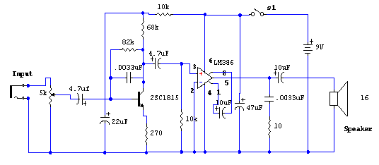
The primary component of this circuit is the LM386 amplifier chip. It also incorporates a transistor input to buffer the input signal and provide additional gain for the LM386. This compact unit has proven useful in various scenarios, particularly...
If you have ever used a 12V flasher relay system, typically a mechanical type, for general automotive applications, today we will attempt to build a 12V flasher relay circuit. The 12V flasher relay circuit is a crucial component in automotive...
The most common application for the NTC thermistor is temperature measurement. Accurate temperature measurement can easily be accomplished by interfacing a Wheatstone Bridge, 6K/30K ohm thermistor network and a digital voltmeter integrated circuit as illustrated in Figure 5. The...