
Motorola VWA63 Auto Radio
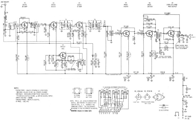
The Motorola VWA63 Auto Radio utilizes a superheterodyne architecture, which is a common design for AM radios that enhances the quality of signal reception and selectivity. The circuit typically consists of several key components: an antenna, a radio frequency (RF) amplifier, a mixer, an intermediate frequency (IF) amplifier, a demodulator, and an audio amplifier.
The antenna captures AM radio waves, which are then fed into the RF amplifier. This stage amplifies the weak signals received from the antenna. The amplified RF signal is then mixed with a locally generated frequency from a local oscillator within the mixer stage. This process converts the signal to an intermediate frequency, which is easier to process.
After mixing, the resulting signal is passed to the IF amplifier. This stage further amplifies the intermediate frequency signal while providing improved selectivity and sensitivity. The demodulator then extracts the audio information from the IF signal. This is typically achieved using envelope detection, which recovers the original audio waveform from the modulated carrier wave.
Finally, the audio amplifier amplifies the demodulated signal to a level suitable for driving the speakers in the vehicle. The schematic for the Motorola VWA63 Auto Radio would detail the specific connections and values of components, including resistors, capacitors, and transistors, that make up each of these stages, ensuring optimal performance for AM broadcast reception.Motorola VWA63 Auto Radio is an automotive type all-transistor superheterodyne AM radio for standard broadcast reception. The following schematic illustrates.. 🔗 External reference
Related Circuits
Automatic fan control circuit. This circuit turns a 12V DC fan or CPU fan on or off based on temperature readings. The temperature can be adjusted using VR1. The automatic fan control circuit operates by monitoring the temperature of...
This compact device serves as a replacement for the input transistors and related circuitry on a single TO-220 style package. A decision was made to substitute the original driver board with a newly fabricated printed circuit board (PCB) designed...
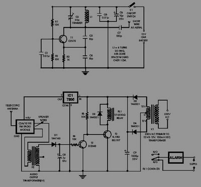
This circuit of an FM radio-controlled anti-theft alarm can be utilized with any vehicle that has a 6 to 12-volt DC supply system. The mini VHF FM transmitter is installed in the vehicle during the night when it is...
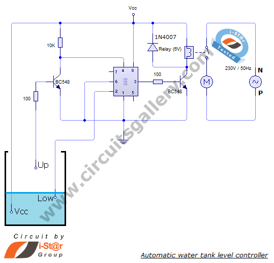
The automatic water level controller circuit is a straightforward engineering project that can automatically switch a domestic water pump on and off based on the water level in a tank. This motor driver circuit can be implemented at home...
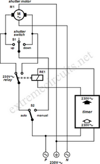
To automate the opening and closing of a rolling shutter using a time-controlled switch, additional wiring will be necessary. To implement an automated system for a rolling shutter, a time-controlled switch can be utilized to manage the operation of the...
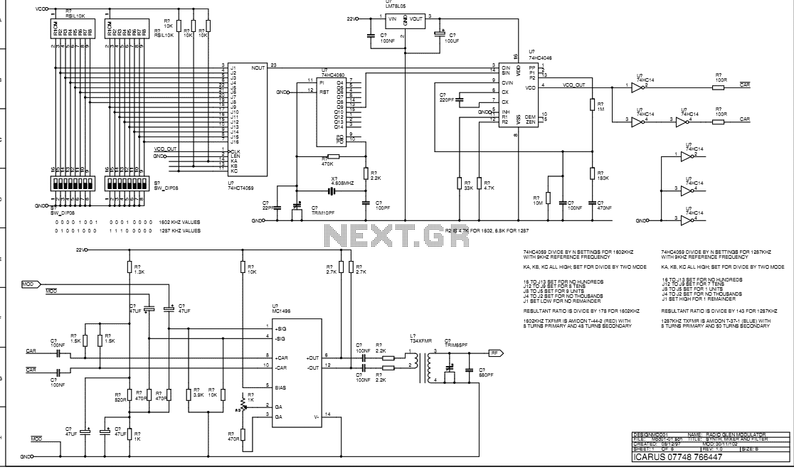
This document describes the transmitter system supplied to Radio Glen for testing as designed and constructed by Henry. The transmitter is supplied in prototype form and has the physical limitations of an instrument constructed using prototyping techniques. The transmitter...