
To Automate Rolling Shutter Motor
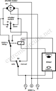
To implement an automated system for a rolling shutter, a time-controlled switch can be utilized to manage the operation of the shutter. The circuit design will involve several key components: a time switch, a relay, and the rolling shutter motor.
The time switch serves as the control unit, allowing the user to set specific times for the shutter to open and close. This device typically features programmable settings, which can be adjusted to meet the user's requirements.
The relay acts as an intermediary between the time switch and the rolling shutter motor. It is essential for handling the higher currents that the motor may draw, ensuring that the time switch, which is rated for lower currents, is not damaged. The relay should be rated appropriately to handle the motor's voltage and current specifications.
Wiring will be necessary to connect these components. The time switch will be connected to the relay's control circuit. The relay's output will then connect to the rolling shutter motor, allowing the relay to control the power supply to the motor based on the time switch's settings.
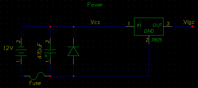
Additionally, it is advisable to include safety features such as fuses or circuit breakers to protect against overloads. Proper insulation and routing of the wires are also crucial to prevent short circuits and ensure reliable operation.
In summary, the automation of a rolling shutter with a time-controlled switch requires careful consideration of the components, wiring, and safety measures to create an efficient and reliable system.If you would like to automate? the opening and closing a rolling shutter with a time controlled switch, a few additional wires will have to be . 🔗 External reference
Related Circuits
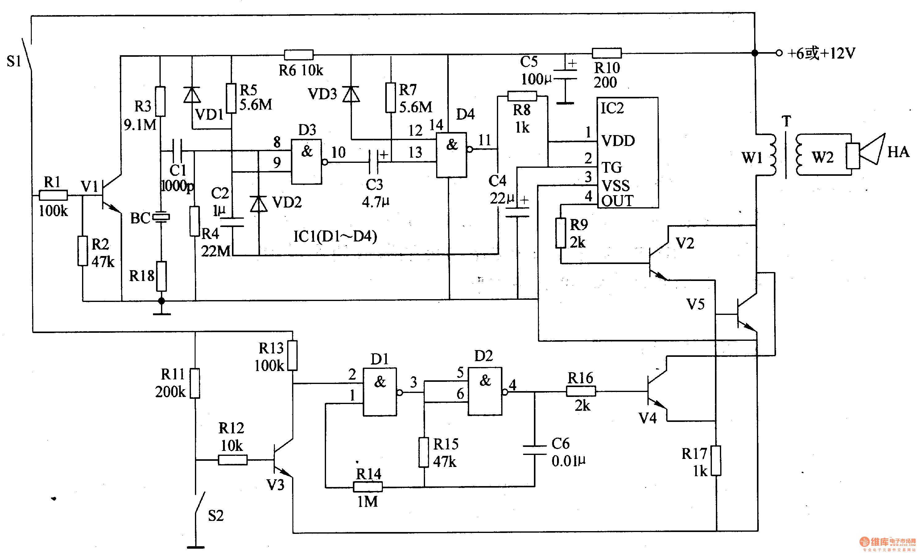
The motorcycle anti-theft alarm circuit consists of several components, including the anti-theft detection circuit, the control circuit, the sound generator, the audio oscillator, and the power amplifier output circuit, as illustrated in figure 7-91. The anti-theft detection circuit is...

Capacitor start single-phase induction motor circuit configuration, in order to form a two-phase rotating magnetic field, starting winding and capacitor in series, the same magnetic field can be formed automatically. The capacitor start single-phase induction motor utilizes a specific circuit...
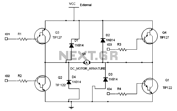
To maintain a constant speed of the motor under varying load conditions, a control application circuit is required. An H-Bridge circuit can be utilized to manage both the speed and direction of the motor. The accompanying diagram illustrates the...
The circuit operates by using a clock signal to drive four D-flip-flops in the control section, which store the on/off state of each current direction for the two stepper motor coils. The flip-flops create a finite state machine (FSM)...
The circuit is based on the SN74LS194 Bidirectional Universal Shift Register and is designed to drive unipolar stepper motors, providing basic control functions such as forward, reverse, stop, and speed adjustment. Direction control is selected by an ON-OFF-ON type...
The logic power and CAN signals enter through pins 3 to 8 of connector N4. These CAN signals are routed to the MCP2551 CAN physical layer integrated circuit (IC), designated as U5. The transmit and receive pins of the...