
Hall Effect Sensor Circuit
The A1302 Hall effect sensor circuit is structured to effectively interface with an Arduino microcontroller, enabling the detection and measurement of magnetic fields. The sensor's design includes an integrated circuit that converts magnetic field strength into a corresponding output voltage. This output is analog in nature, allowing for a continuous range of values proportional to the strength of the magnetic field detected.
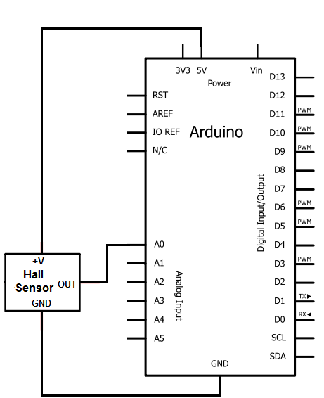
The circuit configuration is straightforward. The A1302's Pin 1 is connected to the positive terminal of the Arduino's 5V output, ensuring that the sensor receives adequate power for operation. Pin 2 is connected to the ground, completing the power supply circuit. Pin 3, the output pin, is connected to one of the analog input pins on the Arduino, which will be used to read the voltage output from the sensor.
In terms of software implementation, the Arduino sketch (code) is crucial for interpreting the sensor's output. The initial setup includes defining the pin modes for the input and output pins, followed by initializing serial communication at a baud rate of 9600, which is standard for many Arduino applications. The main loop of the code continuously reads the voltage from the output pin of the A1302. This reading is then sent to the computer via the serial port, where it can be monitored in real-time.
The use of a USB Type A to Type B cable facilitates the connection between the Arduino and the computer, allowing for seamless data transfer and program uploads. This connection not only powers the Arduino but also enables the user to interact with the device through the Processing software, enhancing the functionality of the circuit.
Overall, this Hall effect sensor circuit exemplifies a simple yet effective method for magnetic field detection, leveraging the capabilities of the A1302 sensor and the Arduino platform for data acquisition and display. The integration of hardware and software components allows for a comprehensive understanding of magnetic field interactions, making it suitable for various applications in electronics and sensor technology.The hall effect sensor we will use in this circuit is an A1302 hall effect sensor manufactured by Allegro. This IC can detect magnetic fields. We will then connect this IC to an arduino, so that we the arduino can read the voltage output by the A1302 and we can display the readings to the computer screen.
When a magnet is placed in the vicinity of the A1302 hall effect sensor, we will see a reading change in the output, signaling that it "knows" a magnet is in its vicinity. The A1302 hall effect sensor is an IC that uses 4. 5-6V as input for operation. This is perfect because the arduino supplies 5V of power, right in between this range. The IC has 3 pins, 2 for the power supply and 1 for the analog voltage output. The output pin provides a voltage output that is linearly proportional to the applied magnetic field.
In order to get the reading of the magnetic field reading, we have to write code to the arduino to read and display this value. The code is shown below. Pin 1 receives positive DC voltage in order for the IC to work. This, again, is voltage between 4. 5-6V. Pin 2 is the ground, so it receives the ground or negative terminal of the DC power supply. Pin 3 is the output of the IC, outputting an analog voltage in porportion to the magnetic field it is exposed to.
Also to do this project we need a USB cable with a Type A connector on one end and a Type B connector on the other end. This is so that we can hook our arduino to a computer and send it code that it can run to display to us the magnetic field reading.
Now that we have this circuit setup, we now connect the USB cable from the arduino to the computer. The type B side of the connector goes into the arduino and the type A side into the USB port of the computer. Now the computer is connected to the arduino. We can now write code in the processing software to give instructions to the arduino. This code first defines the pin connections with the first block of code. The second block sets the baud rate at 9600. T he third block of code is the main loop. This simply reads the analog voltage from the output pin of the A1302 sensor. No conversions or computations are done. The raw value is simply read and displayed. 🔗 External reference
Related Circuits
Today, it is no longer necessary to use discrete components for constructing oscillators. Many manufacturers now offer ready-made voltage-controlled oscillator (VCO) integrated circuits (ICs) that require only a few external components to determine the frequency. An example of such...
The electronic switch consists of the CK-4 type magnetic control switch and the components VT1, R1, and R2. When the bathroom door is closed, the permanent magnet ZT and the reed switch GA come into proximity, which separates the...
During rainy seasons, it can be quite bothersome when the car wipers operate continuously without pause. Have you ever considered implementing speed control for the wipers? While there are wiper control modules available commercially, many of them can be...
The XLR connector facilitates the connection of the microphone's output to the preamplifier circuit. This preamplifier was designed and constructed by Electrical Engineers using discrete components. The signal from the preamplifier is subsequently fed to the Maxim Class-D amplifier....

The operation and circuit diagram of a low-cost amplifier utilizing BC107 and BC148 transistors are explained in detail. The low-cost amplifier circuit employs two types of transistors, BC107 and BC148, which are commonly used for their favorable characteristics in audio...
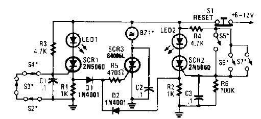
A straightforward high-power alarm driver electronic project can be developed using this circuit diagram. This high-power alarm driver project utilizes a low-power SCR to trigger a high-power SCR. When switches S2, S3, or S4 are opened or switches S5,...