
MP1826 by the LM567 and precision timer circuit

The LM567 is a versatile phase-locked loop (PLL) device that can be configured as a dual-band oscillator in various applications, particularly in communication systems. In the MPI826 configuration, the LM567 operates by generating two distinct frequency outputs, which can be finely tuned to meet specific requirements.
The MP1826 component functions as a frequency divider, effectively reducing the frequency output from the LM567. This division is critical for applications requiring lower frequency signals while maintaining signal integrity. The output from the LM567 can be adjusted in real-time, which provides flexibility in applications where frequency modulation is necessary. This feature allows for dynamic changes in the operating conditions without the need for physical circuit modifications.
The circuit's design emphasizes precision and stability, making it suitable for applications that demand high accuracy in timing and frequency generation. The ability to adjust the oscillation frequency in real-time enhances the circuit's adaptability, allowing it to respond to varying operational demands efficiently. Overall, the combination of the LM567 and MP1826 in the MPI826 circuit exemplifies a robust solution for dual-band oscillation and frequency division tasks in electronic systems.A precision shown by the LM567 timer circuit MPI826 constructed and where LM567 used as a dual-band oscillator. MP1826 acts as a divider in the circuit, the output signal by di viding LM567 achieve long timed. LM567 adjustment of the oscillation frequency can be changed in real time rate time
Related Circuits
IR appliances use pulses (control signals) sent over a modulated IR carrier wave. The carrier wave may be modulated at various frequencies, 36-38KHz being the most popular. Some Satellite receivers use even higher frequencies than this. The IR1 remote...
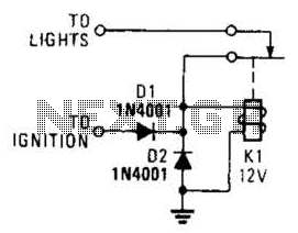
A relay and two diodes are all that is needed; the relay performs the job of a buzzer, so no annunciator is required. When the lights are left on while the ignition is off, the normally closed relay contacts...
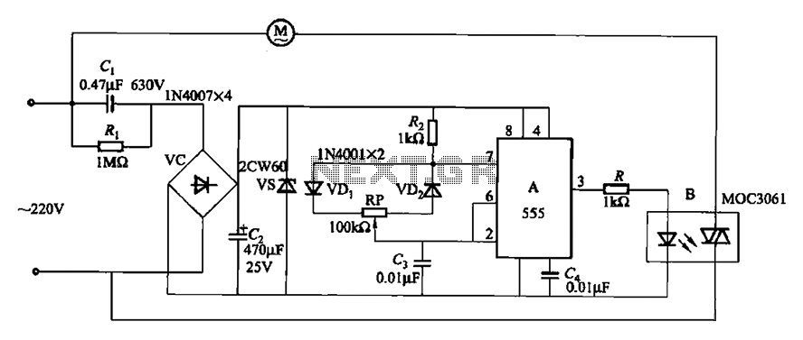
The circuit depicted in Figure 3-9 shares similarities with Figure 3-8, with the distinction that the zero-off MOC3061 type photoelectric coupler is directly connected to control the operation of the fan. The circuit utilizes the MOC3061, a phototransistor optoisolator, which...
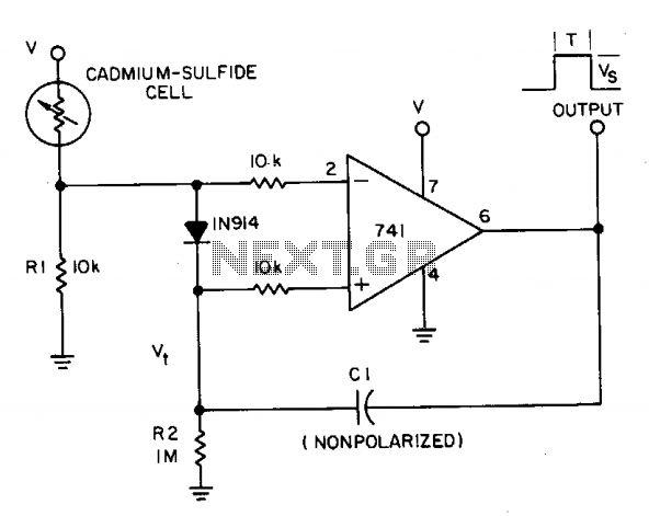
A photocell circuit provides automatic threshold adjustment. Monostable action prevents undesired retriggering of the output. With only one op amp IC, the circuit offers automatic adjustment of its trigger level to accommodate various light sources, changes in ambient light,...
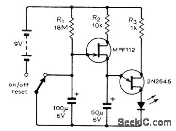
The following circuit illustrates a flashing LED egg timer circuit diagram. This circuit utilizes 2N2646 transistors and features an MPF112 FET. The flashing LED egg timer circuit operates as a visual timer, providing an indication of elapsed time through the...
The Accu charger circuit is straightforward and simple to construct, requiring no more than ten components. In addition to its ease of assembly, this charger circuit is also cost-effective and highly efficient. The circuit requires a power supply from...